
When you’re ready to develop a custom rubber part, you’ll usually run into a question pretty quickly: Which rubber molding method should you use?
What you need to know is that the part’s structure, rubber compound, metal inserts, critical dimensions, vulcanization characteristics, and quality requirements will all influence the final choice. Even if two products look similar, they may require completely different processes due to differences in operating environments and annual demand.
The three common rubber molding methods for thermoset rubber compression-molded parts are:
- Rubber Compression Molding: The weighed, uncured rubber compound is placed directly into a heated mold cavity, and the mold is closed and pressurized to complete vulcanization.
- Rubber Transfer Molding: The rubber compound is placed in a separate feed chamber and then forced through a runner into the closed mold cavity by a plunger.
- Rubber Injection Molding: The injection unit conveys, preheats, and meters the rubber compound, then injects it into a closed, heated mold to complete vulcanization.
All three methods can produce reliable molded rubber parts. The distinction lies not in which method is “absolutely more advanced,” but in which one can meet your project’s requirements with reasonable mold investment, consistent quality, and an acceptable unit cost.
What is rubber molding?
Rubber molding involves placing unvulcanized rubber compound into a mold with a specific shape. Under the combined action of temperature, pressure, and time, the material fills the mold cavity and undergoes vulcanization or cross-linking, ultimately producing rubber parts with elastic and stable properties.
Once the rubber compound has completed vulcanization, it cannot be remelted and reprocessed like thermoplastics.
Since vulcanization curves, flow characteristics, and heat resistance windows vary depending on the formulation, this article will not provide a fixed set of temperatures, pressures, or cycles applicable to all rubbers. The actual parameters used in production should be determined based on material data, trial molding results, and product performance requirements.
Rubber Compression Molding
How Does Rubber Compression Molding Work?
Rubber compression molding is the most straightforward of the three methods.
Before production begins, an operator or automated equipment prepares rubber preforms to the specified weight and shape. The mold opens, and the rubber is placed into the heated mold cavity; the mold then closes and pressure is applied, causing the rubber to flow within the cavity.
Once the set curing time is reached, the mold opens, and the part is removed for trimming, cleaning, and any necessary post-curing treatment.
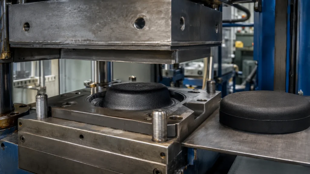
The complete process typically includes:
- compounding the rubber and verifying the batch;
- Weighing and forming preforms;
- Placing the rubber compound and any necessary metal inserts into the mold cavity;
- closing the mold, applying pressure, venting, and vulcanization;
- Demolding, trimming, cleaning, and inspection;
- Determine whether post-vulcanization is required based on material and performance specifications.
When closing the mold, there must be sufficient rubber compound to ensure the mold cavity is fully filled; therefore, a small amount of excess material typically flows into the parting line or overflow channels, forming flash. This does not indicate a loss of process control, but the location, thickness, and subsequent trimming methods for the flash must be clearly considered during the mold design phase—in particular, the parting line must not interfere with sealing surfaces, assembly surfaces, or primary appearance surfaces.
For which applications is rubber compression molding suitable?
Compression molding is generally suitable for custom rubber parts with relatively simple structures, large dimensions, thick cross-sections, or small- to medium-volume production requirements. It is also commonly used for rubber vibration-damping pads, seals, buffer blocks, vibration-isolation mounts, and certain rubber-to-metal bonded parts.
Compared to the other two rubber molding methods, compression molds typically have a simpler structure, and upfront costs are easier to control. This makes it suitable for projects involving prototype validation, rapid product iteration, or projects where the lifetime demand is insufficient to justify the cost of a complex injection mold.
Key Advantages of Compression Molding
- Relatively simple mold design, with typically lower initial investment;
- Well-suited for large-sized, thick-walled, and relatively simple parts;
- Capable of processing a wide range of solid rubber formulations;
- Suitable for small-batch, prototype, and medium-volume production;
- Process tuning is relatively straightforward by adjusting the weight and orientation of the preformed blanks;
- It can produce rubber-metal composite parts, but requires proper design of the insert positioning and bonding systems.
Limitations of Compression Molding
Compression molding often requires the preparation and placement of preforms, involving a high degree of manual labor. The rubber compound must flow a relatively long distance under pressure within the mold cavity; when parts have complex structures, significant variations in wall thickness, or numerous deep cavities, the risk of short shots, trapped air, and uneven filling increases.
Therefore, “inexpensive molds” do not necessarily mean the lowest total project cost. If parts require extensive manual trimming or if consistency across multiple cavities is difficult to maintain, the lower mold investment may be offset by higher labor costs, scrap rates, and delivery fluctuations.
Rubber Transfer Molding
How does rubber transfer molding work?
Transfer molding can be understood as a process route between compression molding and injection molding. The rubber compound is not placed directly into the product cavity but is first loaded into a transfer chamber on the mold. After the mold closes, a plunger applies pressure to the rubber compound, causing the softened rubber to flow through the gate and runner into one or more closed cavities, where it undergoes vulcanization.
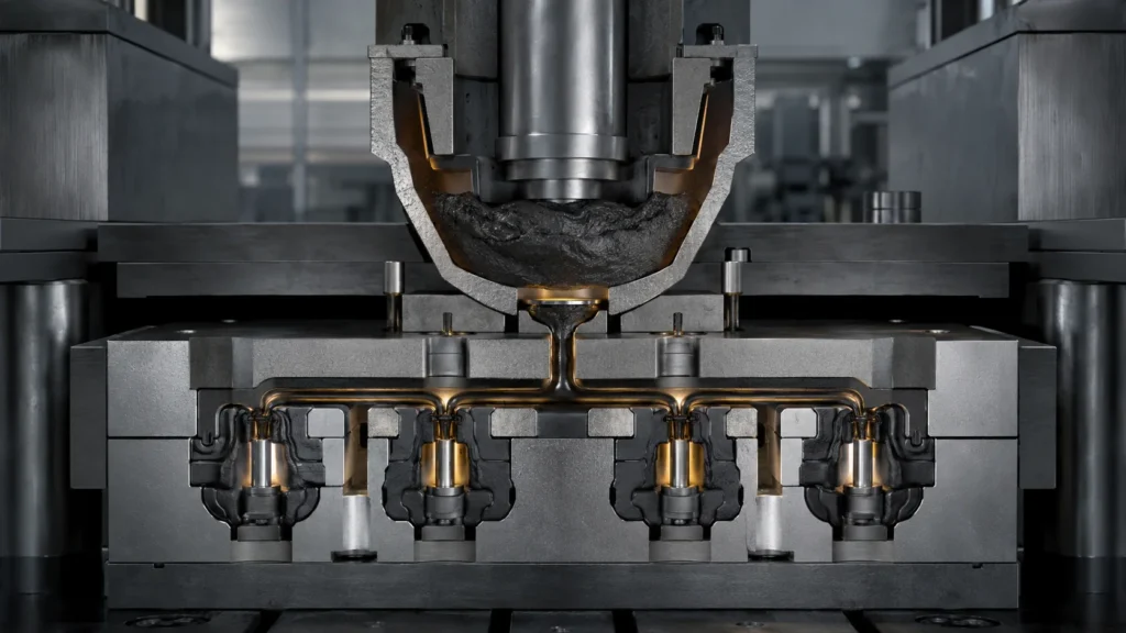
Typical steps include:
- Preparing a preform of rubber compound weighing the specified amount;
- Cleaning and positioning the metal or plastic inserts to be overmolded;
- Closing the product mold cavity and placing the rubber compound into the transfer chamber;
- Pressing the rubber compound through the runner and gate using a plunger;
- Maintaining pressure and completing vulcanization;
- Open the mold to remove the part, and remove the core, runners, and flash;
- Conduct inspections for appearance, dimensions, adhesion, and functionality.
Since the mold cavity is closed before filling, the rubber compound can enter narrow areas through the designed gate, and the parting line of the product is also easier to control. For multi-cavity parts, products with complex shapes, and rubber parts containing inserts, transfer molding often strikes a good balance between mold cost and production stability.
Why is transfer molding commonly used for rubber-to-metal bonded parts?
If your product includes a metal skeleton, sleeve, stud, or mounting plate, it is necessary not only to ensure the rubber material fills the mold cavity but also to prevent the insert from shifting during flow and compression, while ensuring a stable bond between the rubber and the treated metal surface.
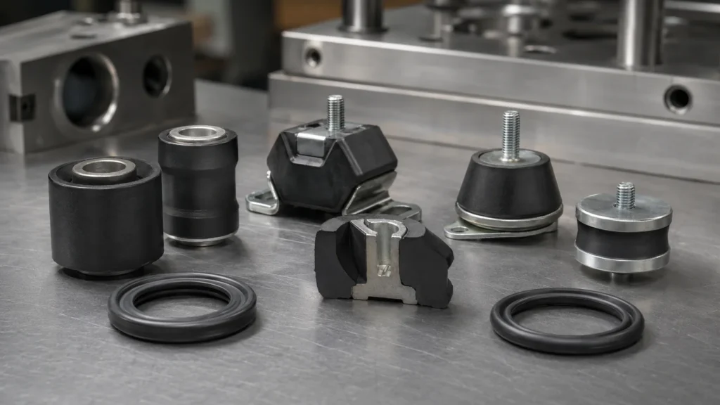
Transfer molding uses closed cavities and controlled runners, which facilitate the design of insert positioning structures and allow the rubber compound to encapsulate the metal surface from a predetermined location. As a result, it is frequently used for rubber shock absorbers, rubber bushings, electrical insulation components, and structurally complex rubber-to-metal composite parts.
However, this does not mean that simply using transfer molding guarantees bond strength. Metal degreasing, surface treatment, adhesive selection, coating consistency, rubber flow, and the vulcanization window still determine the final result.
Key Advantages of Transfer Molding
- It is easier to fill details, deep cavities, and complex geometries compared to compression molding;
- Suitable for multi-cavity molds and products containing metal or plastic inserts;
- Gate locations and rubber flow paths are easier to engineer;
- Product parting lines and flash locations are generally easier to control;
- For medium-volume projects, it strikes a balance between mold investment, part complexity, and consistency.
Limitations of Transfer Molding
A portion of the vulcanized material remains in the material chamber, cake, gate, and runner, so material utilization in transfer molding is not necessarily superior to that of compression molding. Molds are also more complex, requiring control of temperature rise, shear, and residence time of the compound in the runner; otherwise, issues such as premature scorching, insufficient filling, or reduced strength in the flow-joined areas may occur.
For higher-cost formulations such as FKM, runner scrap can significantly impact total costs; for products with very high annual demand, the loading and cleaning cycles of the transfer process may also become efficiency bottlenecks. In such cases, it is necessary to evaluate whether injection molding is a more suitable alternative.
Rubber Injection Molding
How Does Rubber Injection Molding Work?
Rubber injection molding uses an injection unit to continuously feed and meter the rubber compound. For common solid thermosetting rubbers, the rubber strip enters the barrel, where it is plastified, preheated, and metered by the screw, then injected through the nozzle and runner into the closed, heated mold.
The barrel temperature must be carefully controlled to prevent premature vulcanization of the rubber compound before it enters the mold cavity; once inside the heated mold, the compound undergoes cross-linking within a predetermined timeframe.
The feeding method for liquid silicone rubber (LSR) injection molding differs. Components A and B are typically mixed by a metering system according to the formulation requirements and then injected into a heated mold for curing. However, whether processing solid rubber or LSR, the core principle involves the controlled management of feed rate, injection speed, pressure, temperature, and curing cycle within a closed mold cavity.
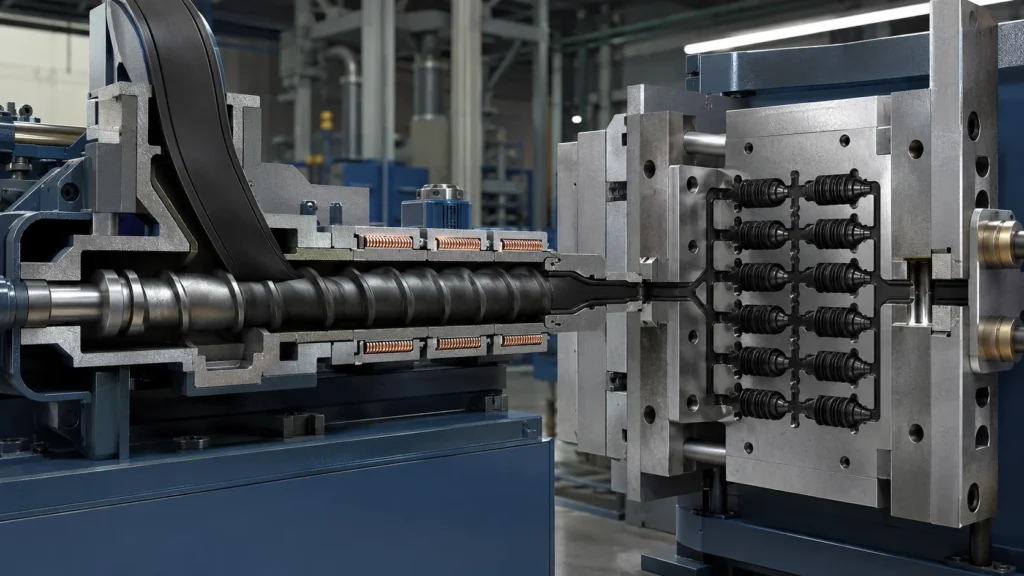
A typical process includes:
- Feeding of the rubber compound or two-component liquid silicone rubber;
- Metering, mixing, or screw pre-plasticization;
- Closing the mold and confirming insert positioning;
- Injection at the set speed and pressure;
- Curing in a heated mold;
- Mold opening, ejection, or removal of the product;
- Trim, post-process, inspect, and record the batch.
For which projects is rubber injection molding suitable?
Injection molding typically offers advantages when product demand is high, the structure is complex, consistency across multiple cavities is critical, or when delivery cycles and automation levels significantly impact the project’s cost-effectiveness.
Common products include precision seals, dust boots, diaphragms, automotive rubber parts, electronic connector seals, small vibration-damping parts, and liquid silicone rubber (LSR) components.
Since the rubber compound is preheated to a certain extent before entering the mold, it typically reaches the vulcanization state more quickly once inside the mold cavity. Automated metering also eliminates the need to individually prepare and position preformed blanks for each mold, making injection molding more suitable for stable, continuous batch production.
Key Advantages of Injection Molding
- High degree of automation, reducing variations caused by manual loading;
- Injection volume, speed, pressure, and temperature can be recorded and repeated;
- Suitable for complex, small, multi-cavity products with high production volumes;
- Preheating the compound helps shorten the in-mold curing cycle;
- It is more conducive to stable cycle times, batch consistency, and traceable production;
- When using a well-designed cold runner or runnerless system, it can reduce some runner scrap.
Limitations of Injection Molding
Initial investments in injection molding equipment, molds, cold runner systems, and automated part removal solutions are typically higher. The compound must also be suitable for the flow, shear, and temperature conditions during the injection process, and the mold gates, venting, and runner balance must be thoroughly validated.
If the process window is not properly defined, issues such as scorching, trapped air, short shots, flash, gate marks, or variations between cavities may occur.
If production volumes are low and designs are still changing frequently, the cost of expensive and complex multi-cavity injection molds may not be effectively amortized. Therefore, the value of injection molding derives from total lifecycle volume and stable production, rather than simply from “more advanced equipment.”
A Quick Comparison of Three Rubber Molding Methods
| Comparison Factors | Compression Molding | Transfer Molding | Injection Molding |
| Method of Feeding the Compound into the Mold Cavity | Preformed blanks are placed directly into the open mold cavity | Compound is forced from the transfer chamber into the closed mold cavity via the runner | The injection unit injects metered material into the closed mold cavity |
| Relative to mold insertion | Typically lower | Typically moderate | Typically high |
| Automation potential | Low to moderate | Moderate | High |
| Suitable part complexity | Simple to moderate | Medium to complex | Medium to complex |
| Typical project size | Small to medium batches | Medium-volume | Medium-to-high volume to high volume |
| Metal Inserts | Yes, but positioning must be carefully considered | Very suitable for complex overmolded parts | Suitable, but requires reliable positioning and runner design |
| Significant material loss | Preform overmold and flash | Material cakes, runners, gates, and flash | Runners, gates, and trial mold losses, depending on system design |
| Major Quality Risks | Trapped air, short shots, flash, and operator-related variations | Scorching, runner scrap, gate and insert misalignment | Runner imbalance, shear heating, trapped air, and parameter fluctuations |
| Most Typical Advantages | Cost-effective tooling; suitable for large or simple parts | Balanced solutions for complex geometries and insert-molded parts | High automation, fast cycle times, and batch consistency |
This table is intended for preliminary assessment but does not replace an evaluation of drawings, materials, and operating conditions. The flow properties of the rubber compound, vulcanization curves, part wall thickness, and insert structures may all cause the final recommendation to differ from the general guidelines in the table.
How to Choose the Most Appropriate Rubber Molding Method?
If you are comparing compression, transfer, and injection molding, consider the following seven questions one by one.
What rubber material is used for the part?
NR, EPDM, NBR, CR, FKM, and silicone rubber differ in terms of flowability, scorch resistance, vulcanization rate, shrinkage, and demolding performance. Even for the same geometry, the optimal rubber molding method may change when a different compound is used.
Material selection should first meet service requirements such as resistance to oil, temperature, ozone, media, dynamic fatigue, or compression set, and then confirm whether it can reliably adapt to the target process.
Just how complex is the structure?
Do not focus solely on the part’s outer contour. Deep holes, thin walls, sudden changes in wall thickness, fine ribs, undercuts, long flow paths, and enclosed air pockets can all affect filling and venting.
A simple, large-sized vibration-damping pad may be suitable for compression molding; a sealing assembly with multiple fine features may be better suited for transfer or injection molding.
Does it contain metal or plastic inserts?
Rubber-to-metal bonded parts require simultaneous solutions for insert positioning, surface treatment, adhesives, compound flow, and interface venting.
All three processes can be used for rubber-over-metal applications, but transfer molding and injection molding typically offer greater process design flexibility when inserts are complex, the overmolded area is large, or high consistency is required across multiple cavities.
What are the annual demand volume and product lifecycle?
Do not base your process selection solely on the volume of the initial order. If the product will be in stable production for many years, the higher mold investment can be recouped through shorter cycle times, reduced labor, and more consistent yield rates.
If the design is still in the validation phase, it is generally safer to first use a mold with a simpler structure to verify functionality.
Which dimensions are truly critical?
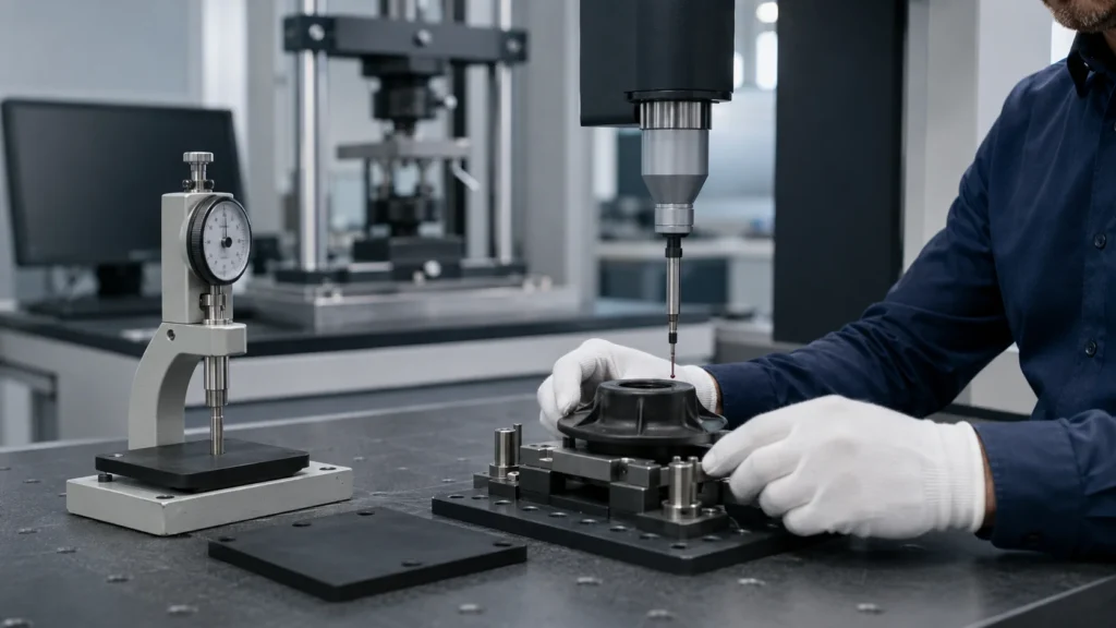
Rubber is a deformable material, and its dimensions are affected by the compound formulation, shrinkage, the mold, parting lines, temperature, and measurement methods. Do not directly apply the tolerance conventions used for metal parts to molded rubber parts.
First, identify the critical dimensions related to sealing, fit, positioning, and assembly, then determine reasonable tolerances based on applicable standards such as ISO 3302-1 and the supplier’s process capability.
What are the constraints regarding flash, gates, and appearance?
If the parting line cannot be located on a sealing surface, or if gate marks would interfere with assembly, their placement must be determined during the DFM phase.
Many issues that appear to be “molding defects” actually stem from a failure to clearly define flash grades, surface requirements, and acceptable trimming methods during the design phase.
Is the primary concern the mold cost or the total cost?
A reliable comparison should include:
Total Lifecycle Cost = Mold Amortization + Materials and Scrap + Machine Cycle Time + Labor and Trimming + Inspection Costs + Scrap and Rework + Delivery Risk
Compression molds have lower upfront costs, but if each product requires significant manual trimming, their long-term costs may not be the lowest; injection molds require a higher initial investment but may result in lower unit costs for stable, high-volume projects. Transfer molding often falls between the two, offering a compromise for complexity, inserts, and production volume.
Three Typical Application Scenarios
Scenario 1: Large-sized rubber vibration-damping mounts with simple structures and limited demand
If the part has a thick cross-section and a simple shape, and the key requirements focus on hardness, load-bearing capacity, dynamic performance, and rubber-to-metal adhesion—rather than extremely short production cycles—compression molding is usually worth evaluating first.
This approach avoids premature investment in complex injection molds for projects that have not yet reached scale.
Scenario 2: Complex rubber-to-metal assemblies with sleeves and mounting plates
When the rubber compound needs to flow around inserts into multiple areas, and insert positioning, bonding boundaries, and venting are critical, transfer molding often makes it easier to design a stable gate path.
If production volumes increase further, the economic feasibility of switching to injection molding can also be evaluated.
Scenario 3: Small, precision seals; multi-cavity continuous production
If the product has a complex structure, high demand, and batch consistency, cycle time, and process documentation are critical, rubber injection molding is typically more suitable.
For LSR precision parts, production plans should also be designed individually, taking into account metering and mixing, cold runners, cleanliness, and post-vulcanization requirements.
These scenarios are not set in stone. The final choice must still be confirmed based on material testing, mold flow and venting analysis, trial mold results, and cost modeling.
Process Names Are No Substitute for Quality Control
Even if the correct rubber molding method is selected, products may still fail if the control of the compound, mold, and vulcanization process is unstable. For custom compression-molded rubber parts, the following aspects are more important than the mere name of the equipment:
- Compound batch control: Verify the formulation, mixing condition, hardness, and necessary vulcanization characteristics;
- Pre-forming or metering consistency: Prevent material shortages, excessive flash, and variations between cavities;
- Mold temperature uniformity: Avoid localized under-curing or over-curing;
- Pressure, time, and venting: Ensure proper filling and the release of air and volatiles from the mold cavity;
- Runner and gate design: Control flow balance, shear heating, and the weld line;
- Metal Insert Preparation: Manage degreasing, surface treatment, adhesives, and clamping positions;
- Post-curing and cleaning: Performed according to specific material and application requirements;
- Inspection and traceability: Correlate dimensions, appearance, material lots, and key process parameters.
For dimensional tolerances, refer to the current ISO 3302-1:2014; for geometric tolerances, refer to ISO 3302-2:2022. North American projects also frequently use the ARPM MO-1 Rubber Handbook as a common language for drawings, tolerances, flash, and quality communication.
However, standards provide only a baseline and cannot replace manufacturability assessments and mutual confirmation specific to individual parts.
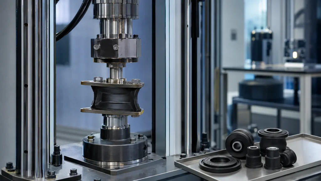
Functional validation should be determined by the product’s intended use. Seals may require greater focus on compression set, media aging, and leakage; vibration-damping components may require greater focus on static stiffness, dynamic stiffness, fatigue, and bond strength; and outdoor rubber components may also require validation for ozone, temperature, and weather resistance.
Quality requirements are only meaningful when test items are directly correlated with actual failure modes.
Five Common Misconceptions in Component Selection
Misconception 1: Injection molding always produces better quality than the other two processes
Injection molding is easier to automate and ensures parameter repeatability, but quality still depends on the material, mold, runner system, venting, and vulcanization window. For simple, large parts or low-volume products, a well-established compression molding process may be more reliable and cost-effective.
Misconception 2: Compounds are interchangeable as long as they have the same hardness
Shore A hardness is merely one indicator of a material’s resistance to indentation. Even if two compounds have the same hardness, they may differ significantly in terms of oil resistance, temperature resistance, fatigue resistance, compression set, and adhesion properties. Determine the required application performance first, then discuss the molding process.
Misconception 3: Transfer molding is always more material-efficient than compression molding
Transfer molding can improve filling and flash control, but the material chamber, cake, and runner create additional vulcanization waste. When material costs are high, calculations should be based on the actual mold layout rather than the process name alone.
Misconception 4: The Tighter the Dimensions Are Specified, the More Professional the Drawing
Unnecessary high precision increases costs for molds, inspection, and scrap. Truly professional drawings distinguish between critical functional dimensions and general dimensions, and clearly specify measurement conditions and acceptance criteria.
Misconception 5: Determining the equipment first, then adapting the material and structure to fit it
The correct sequence is to first understand the function, environment, loads, and service life, and then determine the materials, structure, forming methods, and validation plan.
Sacrificing product requirements to accommodate a specific piece of equipment often shifts costs to subsequent rework and failures.
Summary
Compression molding, transfer molding, and injection molding each address different production challenges: compression molding emphasizes tooling economy and versatility; transfer molding excels at handling complex fill patterns and overmolding of inserts; while injection molding offers greater advantages in automation, production cycle time, and batch consistency.
A truly sound choice requires a comprehensive analysis of materials, structure, critical tolerances, demand volume, quality verification, and lifecycle costs.
Vista Motion’s production system covers rubber compounding, pre-production batch testing of rubber compounds, metal part inspection and surface treatment, compression molding, transfer molding, injection molding, vulcanization, assembly, and test validation, and is equipped with over 100 pieces of related molding equipment. Vista Motion Production Process
For rubber shock absorbers, rubber bushings, seals, and rubber-metal composite assemblies, we can conduct a manufacturability assessment based on your 2D/3D drawings, application environment, materials and hardness, critical dimensions, insert structure, annual demand, and testing standards, and recommend the most suitable rubber molding method for mass production.
If you currently only have a prototype or a preliminary concept, you can start by providing details on the installation space, load, temperature, contact medium, and target service life. Clearly outlining this information before requesting a quote typically makes it easier to obtain reliable mold solutions, cost estimates, and delivery schedules than simply asking, “Which process is the cheapest?”
FAQ
1. What are the three main methods of rubber molding?
The three most common methods for thermoset molded rubber parts are compression molding, transfer molding, and injection molding. Their main differences lie in how the rubber compound enters the mold cavity, as well as mold setup, automation levels, adaptability to complex structures, and production cycle times. Extrusion and calendering belong to different processing routes and are not included among these three molding methods.
2. What is the difference between compression molding and injection molding for rubber?
In compression molding, pre-weighed rubber compound is placed directly into an open mold cavity, after which the mold is closed and pressure is applied for vulcanization; in injection molding, metered rubber compound is fed into a closed mold via an injection unit. The former typically requires a lower tooling investment and is suitable for simple parts and smaller production runs; the latter offers higher levels of automation and repeatability and is better suited for complex, multi-cavity, and larger-volume projects.
3. What is rubber transfer molding?
Transfer molding involves first placing the uncured rubber compound into a separate chamber, then using a plunger to force the compound through runners and a gate into a closed mold cavity. It allows for easier filling of fine details than direct compression and facilitates the positioning of metal inserts, making it commonly used for complex rubber parts and rubber-to-metal overmolded assemblies.
4. Which rubber molding method has the lowest cost?
There is no single answer that applies to all products. Compression molding typically has lower initial costs, but labor, cycle time, and trimming costs may be higher; injection molding requires a higher upfront investment but can reduce unit costs in high-volume production; transfer molding falls somewhere in between. It is important to compare the total lifecycle costs of the mold, materials, labor, yield, and inspection.
5. Which method is best suited for high-volume rubber parts?
For products with stable designs, high demand, complex structures, or strict consistency requirements across multiple cavities, rubber injection molding is usually worth evaluating. However, the economic threshold for “high-volume” production depends on part size, curing cycle time, number of mold cavities, material cost, and automation solutions; it cannot be determined by a fixed quantity.
6. Can NR, EPDM, NBR, FKM, and silicone rubber be processed using all three methods?
Many formulations can be processed using more than one molding method, but not every specific formulation is equally suitable for compression, transfer, and injection molding. Compound flowability, scorch resistance, cure rate, shrinkage, and demolding performance all influence the choice. The material must first meet the requirements of the application environment, and manufacturability must then be confirmed through process trials.
7. Which molding process should be used for rubber-to-metal bonded parts?
All three processes can be used to produce rubber-to-metal bonded parts. Compression molding may be considered for simple, large-sized components or small- to medium-volume production runs; products with complex overmolding, multi-cavity designs, or high insert positioning requirements are typically better suited for transfer or injection molding. The final bond strength also depends on metal surface treatment, the bonding system, mold venting, and vulcanization control.
8. Do injection-molded rubber parts always have the tightest tolerances?
Not necessarily. The injection process generally promotes process repeatability, but actual tolerances are still determined by a combination of material shrinkage, part geometry, mold precision, parting lines, runner balance, and measurement methods. Supplier capability should be evaluated based on critical functional dimensions specified in the drawings, rather than relying solely on the process name for assurance.
9. Why do molded rubber parts sometimes exhibit flash, short shots, or bubbles?
Flash may be related to excess compound, clamping force, mold fit, or vulcanization conditions; short shots are usually associated with insufficient metering, flow resistance, venting, or premature scorching; bubbles and voids may result from trapped air, volatiles, contamination, or improper venting design. The root cause must be determined by analyzing the defect location and process records.
10. What information is required when requesting a quote for custom rubber parts?
We recommend providing 2D/3D drawings, material specifications or operating environment, Shore hardness, critical dimensions and tolerances, color, specifications for metal or plastic inserts, operating temperature, contact media, static and dynamic loads, testing standards, initial order quantity, annual demand, and target service life. The more complete the information provided, the easier it will be for suppliers to offer reliable DFM, process, and pricing recommendations.
