Scope of Application: Structural vibration control for common rotating/reciprocating equipment such as pumps, cable holders, compressors, motors, generators, machine tools, vehicle control arms, and electronic equipment cabinets (excluding active isolation and complete designs for special military-grade shock spectra).
Three Key Factors for Selecting Anti-Vibration Mounts
1) Load (actual load per support point)
2) Excitation frequency (disturbing/forcing/driving frequency, especially the lowest operating frequency)
3) Target isolation efficiency/allowable transmission rate (how much structural vibration transmission you aim to reduce)
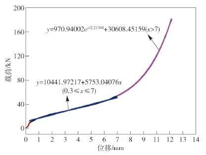
The industry’s mainstream selection approach involves first calculating static deflection using the load-displacement curve, then mapping this static deflection onto an isolation efficiency chart for preliminary selection.
Use “frequency ratio” to avoid resonance before discussing isolation performance
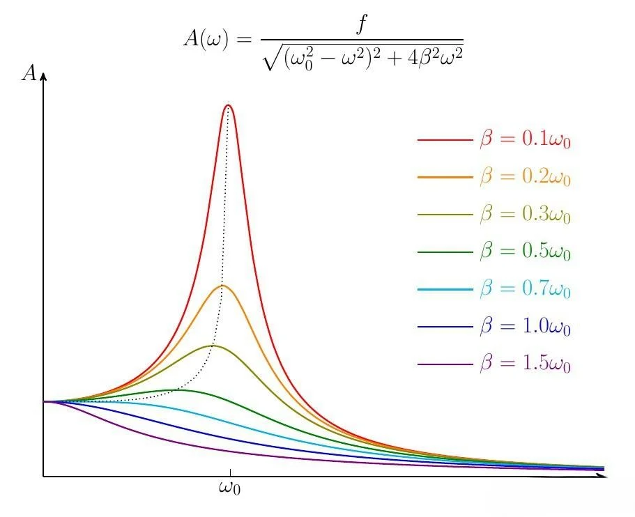
The key metric for isolation systems is Transmissibility, which fundamentally represents the ratio of “output/input” vibrational energy or force.
Pay particular attention to three critical ranges:
- Resonance points: When excitation frequency equals the system’s natural frequency (fd/fn=1), resonance causes a significant peak in transmissibility that must be avoided.
- Amplification Zone: At insufficient frequency ratios, vibrations are amplified rather than isolated. For instance, when disturbance frequencies are less than approximately 1.4 times the natural frequency, input vibrations may not be attenuated but instead amplified and transmitted to the foundation/frame/superstructure. This manifests intuitively as “more vibration despite damping installation.”
- Isolation Zone: When the frequency ratio exceeds √2 (approximately 1.414), the transmission ratio again falls below 1, and the system begins to exhibit isolation effects. Engineering practice often targets higher frequency ratios to achieve stable and significant isolation (e.g., within the range of 2.5–4.5).
Empirical “Quick Rule”: Many engineering selection manuals recommend setting the “excitation frequency/natural frequency” ratio to around 3 to balance effectiveness and cost.
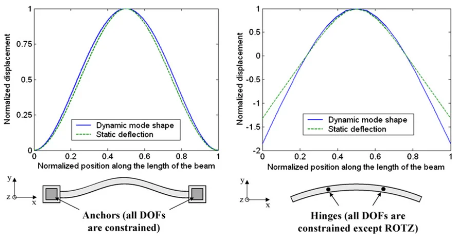
Reducing Natural Frequency via Static Deflection
Static deflection refers to the displacement of the isolator under static load (compression or shear deformation), serving as the bridge between “load” and “natural frequency/isolation efficiency.”
Two common engineering conclusions guide preliminary selection:
- Greater static deflection yields lower natural frequencies, making vibration isolation easier to achieve (though displacement, stability, and structural strength requirements increase).
- For organic materials like rubber, dynamic modulus typically exceeds static modulus. Therefore, estimating natural frequency based solely on static deflection often yields overly optimistic results. Final verification requires dynamic stiffness/actual testing.
Anti-Vibration Mount Selection Process
Step 1: Define Objectives and Boundaries
Clearly identify whether you are addressing “structural vibration/noise transmission” or “equipment displacement/impact protection.” Anti-vibration mounts primarily interrupt and attenuate structural vibration transmission but do not automatically eliminate the vibration source itself.
Step 2: Collect Input Data
Prepare at least these 8 data points: total weight, center of gravity location and height, number and geometry of support points, equipment speed range/minimum operating speed, presence of gearboxes (use the lowest frequency of the final excitation source), mounting orientation (compression/shear/tension), environmental medium (oil/coolant/ozone/outdoor), and allowable displacement/end-of-travel requirements.
When multiple excitation frequencies exist, prioritize the lowest frequency: isolating the lowest frequency typically isolates higher frequencies as well.
Step 3: Convert speed to frequency
Common conversion: Hz = RPM / 60.
Example: 1800 rpm corresponds to 30 Hz.
Step 4: Calculate the “actual load per isolator”
Do not simply use “total weight / number of isolators.” Center of gravity displacement can cause individual support points to overload, affecting both vibration isolation performance and service life. Engineering practice typically requires the center of gravity to be positioned near the vertical centerline of the support plane to prevent excessive stress on individual isolators.
Step 5: Determine the frequency ratio first, then derive the “target natural frequency”
Using fd as the lowest excitation frequency, select the frequency ratio r=fd/fn based on the target isolation performance:
- For “noticeable vibration isolation,” r must exceed 1.414.
- For “significant and stable vibration isolation,” engineering practice often adopts r≈2.5–4.5; many selection guides also provide a rough recommendation of r≈3.
Then derive the target fn = fd/r.
Step 6: Select “static deflection” and model using manufacturer load-displacement curves
Procedure:
- Locate the static deflection corresponding to the single-point load on the load-displacement curve;
- Then plot this static deflection on the isolation efficiency chart to read the achievable isolation efficiency or transmission ratio. This is also the simplest pre-selection path recommended by many guides.
Note: If the static deflection is too small, the frequency ratio may be insufficient, potentially falling into the amplification zone or resulting in weak isolation performance.
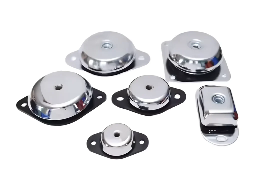
Step 7: Select Isolator Type and Material
1) Rubber-Metal Isolators: High damping, suitable for mid-to-high frequency isolation, cost-effective, simplified installation; however, static deflection is typically limited, making ultra-low frequency isolation more challenging. Dynamic stiffness can cause actual natural frequencies to exceed the “static estimate” based on deflection.
2) Spring Isolators: Easier to achieve large static deflection and low natural frequencies, suitable for low-frequency equipment (e.g., large HVAC units, machinery); however, they have low damping, are more sensitive near resonance zones, and often require damping/limiting designs and on-site verification.
3) Wire rope isolators: Balance vibration and shock absorption with strong environmental adaptability (selection requires supplier data due to significant application variations). Commonly used in shock-prone, posture-changing, or harsh environmental conditions.
(For wall-mounted/side-mounted applications, selection should typically follow the “shear” direction rather than the default vertical compression orientation.)
Step 8: Installation and “Short-Circuit” Risk Inspection
Even the best isolators can be rendered ineffective by piping, cables, or rigid mounting brackets “short-circuiting” their isolation. After installation, perform two critical checks:
- Verify that the static deflection is close to the selected value (too small indicates no isolation, too large poses stability and lifespan risks);
- Conduct a simple comparative test: Compare vibration acceleration or structural noise at key locations before and after isolation. For a more rigorous transfer property assessment, refer to the measurement methodology and terminology framework outlined in the ISO 10846 series.
Common mistakes in selecting anti-vibration mounts
1) Selecting the “stiffest” option based solely on load capacity results in insufficient static deflection and inadequate frequency ratio, yielding isolation performance close to a rigid connection.
2) Focusing solely on rated load capacity without accounting for center of gravity offset, leading to overload at specific corners and premature failure.
3) Neglecting minimum rotational speed/startup conditions causes the low-frequency range to fall into the amplification zone, triggering significant resonance.
4) After installation, short-circuited by piping/wiring harnesses/limiters, resulting in vibration isolation performance that “looks good on paper but fails in the field.”
RFQ
What are the most critical parameters for selecting anti-vibration pads/isolators?
Single-point load, minimum excitation frequency, and target isolation efficiency. The mainstream method is to first determine the static deflection based on the load, then read the isolation efficiency from the static deflection.
Why focus on “minimum rotational speed/minimum frequency” rather than maximum speed?
In multi-frequency scenarios, isolating the lowest frequency takes priority. Once the lowest frequency is isolated, higher frequencies are typically isolated as well.
What frequency ratio fd/fn is required for true vibration isolation?
Theoretically, exceeding √2 (approximately 1.414) enters the isolation zone; engineering practice often adopts 2.5–4.5 to achieve more robust isolation performance.
Under what conditions does resonance occur? How can it be avoided?
Resonance occurs when fd/fn=1, causing a significant peak in transmission ratio. Avoid critical frequencies by increasing static deflection to lower fn, and reduce resonance peaks with appropriate damping.
Is greater static deflection always better?
Increasing static deflection helps lower natural frequencies and enhance vibration isolation. However, it also leads to greater displacement, stability concerns, and increased stress on limiting designs, requiring a comprehensive balance.
Why are “static calculations” for rubber isolators often inaccurate?
Dynamic moduli of organic materials like rubber typically exceed static moduli. Actual natural frequencies may surpass estimates based solely on static deflection. Verification using dynamic stiffness data or testing is recommended.
For wall-mounted/side-mounted equipment, how should the installation orientation of isolators be selected?
Such installations typically operate under shear forces. Selection should be based on shear characteristics and shear load curves, not defaulting to vertical compression.
What do “70%/80%/90% vibration isolation efficiency” values mean in engineering?
Essentially, it indicates the degree of reduction in transmission rate. Many guidelines use efficiency charts to map “static deflection + excitation frequency” to isolation efficiency for rapid pre-selection.
How many isolators are optimal for a single piece of equipment?
Prioritize stability and load distribution (typically 4-point support), then allocate single-point loads based on center of gravity and structural stiffness. Offset centers of gravity may cause overload in individual isolators, requiring layout adjustments.
How can we verify “true isolation” after selection?
Verify that actual static deflection is close to the selected value and conduct vibration comparison tests before and after isolation. For more systematic transmission characteristic measurements, refer to the methodological framework outlined in ISO 10846.