When manufacturing molded rubber parts, many issues appear on the surface to be “dimensional deviations,” but the root cause often lies not in the production process itself, but in an insufficient understanding of molded rubber tolerances during the early stages.
Let me put it more plainly: if you approach rubber molding tolerances with the same mindset as you would for metal parts, the project will likely become more expensive, take longer, and may even enter a cycle of repeated mold revisions and confirmations right from the start. Conversely, if you clearly define molded rubber tolerances, fixed dimensions, closure dimensions, material shrinkage, hardness, and measurement methods from the outset, many of these issues can actually be avoided in advance.
Within the industry, dimensional tolerances for molded rubber parts typically reference the ARPM/RMA grading system; internationally, standards such as ISO 3302-1 are also commonly referenced. ISO 3302-1 remains a valid standard today and applies to solid rubber products produced by molding, extrusion, and calendering.
What are molded rubber tolerances?
Essentially, molded rubber tolerances refer to the permissible range of dimensional variation in molded rubber parts. They are not an excuse for “poor accuracy,” but rather an engineering definition of acceptable variation during the manufacturing process. Because rubber is not a rigid metal, molded parts are subject to variables during molding, vulcanization, demolding, cooling, and measurement. Therefore, rubber part tolerances are inevitable and are generally not as tight as those for CNC-machined metal parts.
This is why you’ll often find an underlying message in many rubber molding tolerance documents: “The tolerance table is a starting point, not a guarantee.” Reference tolerances help designers and buyers quickly establish expectations, but how tight a specific part can be ultimately depends on the part’s geometry, rubber compound formulation, hardness, shrinkage, mold design, flash control, and measurement methods.
Why can’t the logic for metal parts be directly applied to rubber parts?
Because the material logic is completely different.
Metal parts prioritize rigid machining precision, with many dimensions directly controlled through cutting and machining. Molded rubber parts are different; they are influenced by temperature, vulcanization time, mold precision, mold fit, compound variations, shrinkage, and flash thickness. This is especially true for soft rubber, thin-walled, deep-cavity parts, or those with undercuts or asymmetrical structures, where manufacturing variations are typically more pronounced.Simply put, rubber molding tolerances are inherently more dependent on “design for manufacturability” than machining tolerances.
Therefore, a truly experienced engineer will not immediately ask, “Can we achieve ±0.05 mm?” but will first ask three questions:
First, is this a critical functional dimension?
Second, is this a fixed dimension or a closure dimension?
Third, is this dimension required to be tight, or is it simply habitually specified as tight?
By following these three steps, many projects that would otherwise get stuck actually move forward quickly.
What exactly is the difference between a fixed dimension and a closure dimension?
This is the most essential concept in the Molded Rubber Tolerances Guide that you cannot skip.
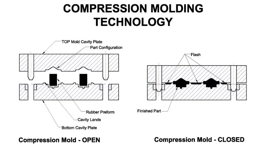
A fixed dimension typically refers to a dimension formed directly from one side of the mold cavity and not directly affected by the thickness of the flash.
Closure dimensions, on the other hand, typically occur in the direction of mold closure and are more significantly affected by the parting line, the mold’s closed state, and variations in flash. Precisely for this reason, closure dimensions are generally more difficult to control than fixed dimensions.
If you’ve worked on projects involving compression-molded rubber tolerances, you’ll intuitively notice that for the same part, the most contentious points on the drawing are rarely some internal lateral dimension, but rather the external height across the parting line, the total thickness, or a dimension that is “formed after the mold closes.”
So my advice is clear:
On the drawing, prioritize clearly marking the truly critical sealing dimensions, assembly dimensions, and fit dimensions separately;
At the same time, relax non-critical dimensions to commercial-grade or generally manufacturable tolerances.
This approach not only better aligns with engineering realities but also helps control mold costs and improve yield rates. Industry data generally indicates that higher precision grades require higher mold accuracy, stricter process control, and higher inspection costs.
How should the common “molded rubber tolerance chart” actually be used?
When many buyers and designers search for a “molded rubber tolerance chart,” what they’re really asking is a more practical question: “Which grade should I use when discussing this part?”
A common industry practice is to classify molded rubber tolerances into different grades, such as A1, A2, A3, and A4. Higher grades typically indicate stricter requirements, higher manufacturing costs, and greater production challenges. For most general industrial applications, commercial-grade tolerances are sufficient; higher grades are typically required for sealing, positioning, critical assembly, or areas demanding high consistency.
You can think of it this way:
A1 / High Precision Grade: Reserved only for truly critical dimensions that must be strictly controlled.
A2 / Precision Grade: Suitable for industrial parts with specific requirements for fit and consistency.
A3 / Commercial Grade: The default and reasonable choice for most standard molded rubber parts.
A4 / Non-critical Grade: Dimensional control is not the primary concern; cost is the priority.
I strongly advise against specifying all dimensions on a drawing as high precision. While this approach may appear “rigorous,” it often sets the project up for failure. High-precision rubber part tolerances do not automatically result in better products; instead, they can lead to higher scrap rates, longer lead times, and more expensive molds.
What factors most influence molded rubber tolerances?
This aspect is often more important than the tolerance table itself.
The Compound Itself
Different formulations, hardness levels, and filler systems all result in varying shrinkage and rebound behavior. Generally speaking, softer materials are more prone to dimensional fluctuations; harder, more stable systems are typically better suited for dimensional control, though this must be evaluated in conjunction with functional requirements.
Part Geometry
Significant variations in wall thickness, numerous sharp corners, deep cavities, thin walls, slender structures, and overmolded metal inserts—all of these can increase manufacturing variability. What you see on the drawing is a single dimension, but what the factory faces on the production floor is the combined result of flow, venting, filling, shrinkage, and demolding.
Mold Design and Precision
The fitting accuracy of mold plates, parting line design, number of cavities, venting, positioning, and the condition of mold wear all directly affect molded rubber tolerances. This is particularly true for multi-cavity molds, where slight variations may inherently exist between cavities.
Process Methods
The control logic for compression-molded rubber tolerances, transfer-molded rubber tolerances, and injection-molded rubber tolerances is not entirely the same. Different processes involve distinct filling methods, venting methods, and process stability, leading to variations in the actual dimensional consistency that can be achieved.
Measurement Methods
This point is particularly easy to overlook. Since rubber is elastic, results may vary depending on the clamping force, measurement location, and dwell time used. For projects requiring high precision, it is best to clearly define the measurement standards, tools, and acceptance criteria before submitting a quote. Industry resources repeatedly emphasize that the higher the tolerance grade, the more critical it is for both parties to clarify measurement and acceptance methods in advance.
How should drawings be written to prevent projects from getting out of control?
If I were to offer one piece of practical advice, I would say: Don’t start by asking, “What’s the absolute minimum we can achieve?” Instead, ask, “Which dimensions are truly worth tightening?”
A relatively safe approach is typically as follows:
- First, divide the part into three tiers.
- The first tier consists of critical dimensions such as those related to sealing, fit, and positioning;
- The second tier consists of dimensions related to appearance or assembly, but not critical to success;
- The third tier consists of non-critical reference dimensions.
Then, assign tighter tolerances to the most critical dimensions, while placing most standard dimensions within the normal range of commercial tolerances. This approach aligns with the engineering logic of rubber molding tolerances and is more conducive to cost control.
If the project is still in the early design phase, it is best to provide suppliers with the following information simultaneously:
- 3D files and 2D drawings
- Material type or target performance
- Hardness range
- Critical sealing surfaces or critical mating surfaces
- Operating environment, such as temperature, media, and compression ratio
- What failure modes concern you most: leakage, loosening, inability to install, or insufficient service life?
At this point, a truly professional supplier won’t simply reply with “We can do it,” but will instead help you assess: which dimensions need to be tightened, which should be relaxed, where parting lines need to be adjusted, where fillets need to be modified, and where flash or shrinkage might cause instability in the closure dimension.
If you’re looking for an answer from a “purchasing perspective”
When selecting molded rubber tolerances, the goal isn’t to choose the tightest possible fit, but rather the range that precisely meets the functional requirements.
Because what you’re really buying isn’t a drawing that “looks tight,” but a rubber part that can be mass-produced reliably, has reasonable costs, meets controllable delivery schedules, and assembles smoothly.
If you specify all dimensions with high precision from the outset, the result is usually not higher quality, but rather higher quotes, slower prototyping, and more difficult mass production. On the contrary, projects that are willing to classify tolerances based on functional requirements and discuss tolerance stack-up based on actual manufacturing processes tend to proceed more smoothly later on.
Summary
Ultimately, the Molded Rubber Tolerances Guide isn’t meant for you to memorize a tolerance chart; it’s designed to help you find a truly actionable balance between design, procurement, and manufacturing.
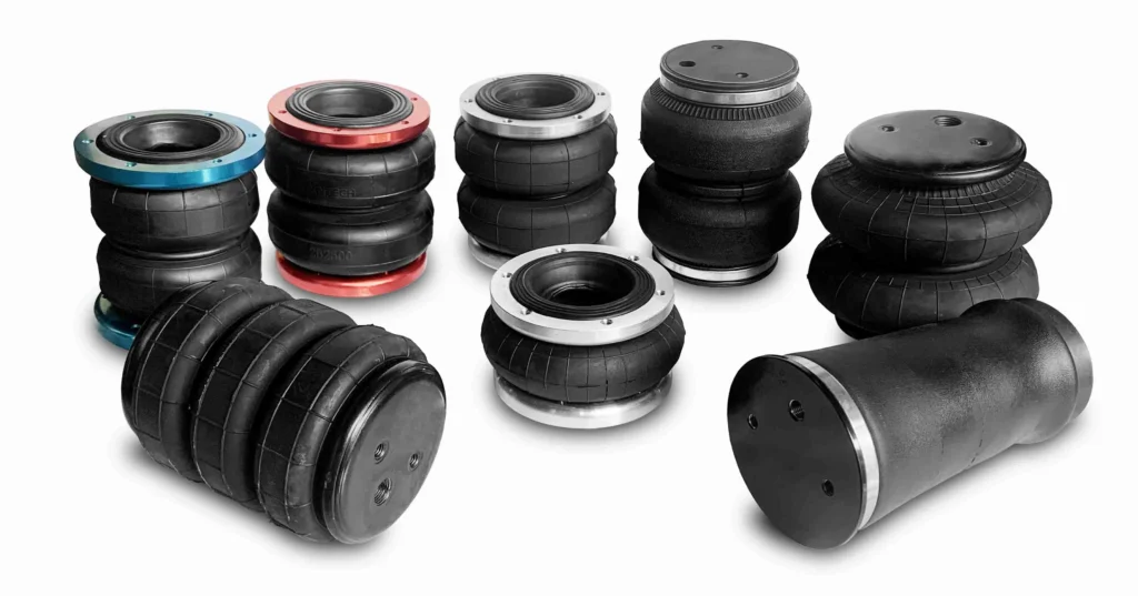
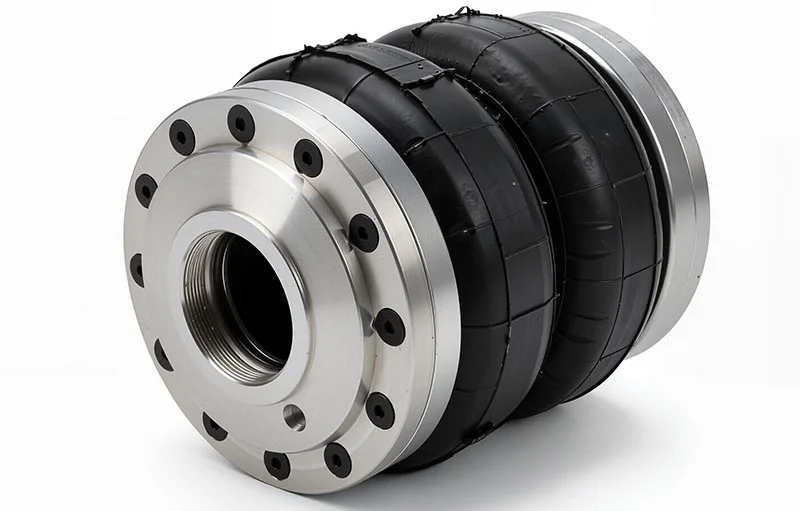
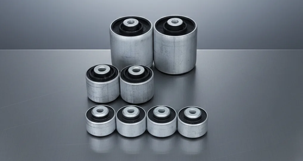
If you’re developing custom rubber parts, rubber seals, vibration dampers, or overmolded metal components—or if you already have 2D/3D drawings but aren’t sure which tolerance grade to use for molded rubber—the most effective approach isn’t to keep guessing. Instead, send us your drawings, material specifications, hardness values, critical dimensions, and application details.
We can start by assessing manufacturability and tolerance risks to help you determine which dimensions need to be controlled, which areas require modification, and which requirements will significantly drive up costs. This way, you’ll receive not just a quote, but engineering feedback that closely reflects the final production outcome.
FAQ
What are molded rubber tolerances?
Molded rubber tolerances refer to the permissible range of dimensional variation in molded rubber parts. Because rubber is subject to various variables during molding, vulcanization, demolding, and measurement, dimensions are typically defined by a ± tolerance range rather than a single, rigid value— —as is common in metalworking.
What is the difference between fixed dimensions and closure dimensions?
A fixed dimension is generally a dimension formed by the mold cavity itself and not directly affected by flash thickness; a closure dimension, on the other hand, typically spans the parting line or is influenced by the mold’s closed state, and is therefore more susceptible to variations in flash and mold closure.
Why are rubber molding tolerances looser than those for metal parts?
Because rubber is an elastic material, it is more significantly affected by temperature, shrinkage, hardness, mold precision, flash, and measurement methods. Many dimensions of metal parts can be directly controlled through machining, whereas rubber molding tolerances rely more on the overall stability of the material and the molding process.
What standard is commonly used for molded rubber tolerance charts?
Common reference systems in the industry include the ARPM/RMA classification of molded rubber tolerances and international standards such as ISO 3302-1. The former is widely used in the North American industrial context, while the latter is an internationally recognized standard for dimensional tolerances of rubber products.
What do A1, A2, A3, and A4 mean in molded rubber tolerances?
They typically represent different tolerance grades. Generally, A1 is tighter, A2 is precision grade, A3 is standard commercial grade, and A4 is more suited for non-critical dimensions or cost-sensitive applications. A higher grade usually implies greater manufacturing difficulty and cost.
Are compression-molded rubber tolerances tighter than injection-molded rubber tolerances?
Not necessarily. Different processes have their own advantages, and the actual achievable tightness depends on the part structure, rubber compound, mold design, venting, shrinkage control, and acceptance criteria. Conclusions should not be drawn based solely on the process name; it is best to evaluate based on specific drawings.
What factors affect rubber part tolerances the most?
The most common factors include compound formulation and hardness, shrinkage, mold precision, mold fit, flash thickness, part geometry, curing time, temperature, and measurement methods. These factors combine to determine the final rubber part tolerances.
Can tighter molded rubber tolerances reduce product failure?
It is possible, but only if these tighter tolerances are truly required for functionality. If all dimensions are simply tightened mechanically, this often only increases mold costs, scrap rates, and delivery pressure, without necessarily improving functional performance. A better approach is to tighten only the critical dimensions.
How should I specify molded rubber tolerances on a drawing?
A prudent approach is to first distinguish between critical and non-critical dimensions, then clearly define which are fixed dimensions and which are closure dimensions, while specifying measurement methods, material hardness, and application scenarios when necessary. This makes it easier for suppliers to provide reliable assessments.
Can a standard tolerance chart guarantee the dimensions of my rubber part?
No. Standard tolerance charts serve more as engineering reference baselines rather than absolute guarantees applicable to all parts. The specific achievable tolerances must still be evaluated in conjunction with the part’s geometry, material, mold, and process capabilities.