
This article begins with the basic principles of mechanical vibration and covers 10 common causes, methods for identifying abnormal vibration, effective solutions, and how to select the right vibration dampers for industrial equipment.
What Is Machine Vibration? Why Does It Occur?
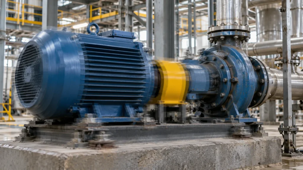
Machine vibration refers to the periodic or non-periodic motion of mechanical equipment or components around a specific point during operation.
Motors, fans, pumps, compressors, gearboxes, and other industrial equipment can all generate vibration due to rotation, reciprocating motion, load variations, or external excitation.
From a mechanical engineering perspective, vibration primarily involves three factors:
- Mass: Determines the system’s inertial response to external forces.
- Stiffness: Determines a structure’s ability to resist deformation and influences the system’s natural frequency.
- Damping: Determines how vibration energy is dissipated and the extent of the system’s response near resonance.
These three factors interact and collectively influence the vibration characteristics of the equipment.
What is the difference between normal vibration and abnormal vibration?
Not all vibrations indicate equipment failure.
For example, reciprocating compressors are subjected to periodic inertial forces and gas forces during operation; vibrating screens rely on specific forms of vibration to process materials. These vibrations are part of the equipment’s design and operating principles.
What really requires attention is whether the vibration exceeds the equipment’s permissible operating range or shows significant changes compared to previous conditions.
You should pay close attention to the following phenomena:
- Unusual shaking, knocking, or grinding noises during machine operation that were not present before.
- A sustained increase in vibration levels under the same rotational speed and load.
- Abnormal increases in the temperature of bearings, couplings, or motor housings.
- Repeated loosening of mounting bolts, or fatigue cracks appearing in supports or piping.
- A decline in the equipment’s machining accuracy, operational stability, or product quality.
- Abnormally severe vibration occurs when the machine starts, stops, or changes speed.
If these symptoms persist, arrange for a professional to inspect the equipment rather than relying solely on listening to sounds or touching the machine housing to diagnose the problem.
What effects can excessive vibration have on machinery?
Abnormal vibration can cause more than just noise.
First, alternating loads increase the stress on bearings, seals, and mechanical joints, and long-term operation may accelerate wear. Second, structural vibrations may propagate outward through the base, frame, and piping, affecting nearby equipment.
For CNC machine tools, precision measuring equipment, and automated production lines, excessive vibration can also reduce machining stability and repeatability.
If equipment vibration leads to connection failure, parts falling off, or structural damage, the issue is no longer just a matter of maintenance costs but may involve personnel and equipment safety.
Therefore, the goal of addressing machine vibration is not to bring all components to a complete standstill, but to keep equipment vibration, structural response, and vibration transmitted to the outside within acceptable limits.
10 Common Causes of Machine Vibration and Their Solutions
Identifying the source of vibration is the first step toward resolving the issue.
The following 10 scenarios cover most common vibration issues in industrial rotating equipment; however, actual failures may result from a combination of factors, so final conclusions cannot be drawn based on a single symptom alone.
Rotor Imbalance
Rotor imbalance is one of the most common causes of vibration in rotating machinery.
If the mass distribution of a fan impeller, rotating shaft, pulley, or other rotating component is uneven, an unbalanced centrifugal force will be generated when the rotor rotates.
As rotational speed increases, this excitation tends to become more pronounced.
Common manifestations:
- Prominent radial vibration.
- The vibration is clearly correlated with the equipment’s rotational speed.
- Fans, pumps, or motors experience increased vibration during high-speed operation.
- Bearings and support structures are subjected to additional alternating loads over the long term.
For example, dust accumulation on the surface of fan blades may alter the impeller’s original mass distribution. Even if the equipment was initially dynamically balanced, new imbalances may develop after prolonged operation.
Solution:
First, inspect the rotating components for dirt buildup, wear, corrosion, damage, or missing counterweights. If any abnormalities are found, address them after safely shutting down the equipment.
For rotors with confirmed imbalance, a professional should use a dynamic balancer to inspect and correct the imbalance.
It is important to note that before performing dynamic balancing, issues such as shaft deflection, assembly eccentricity, and structural looseness should be investigated to avoid misdiagnosing other faults as rotor imbalance.
Shaft Misalignment
In systems where electric motors drive pumps, compressors, and gearboxes, the two interconnected rotating shafts must meet specified alignment requirements.
If there is a deviation in the centerlines of the two shafts, the coupling and its adjacent bearings may be subjected to additional loads, resulting in abnormal vibration.
Misalignment generally takes two main forms:
Parallel misalignment: The centerlines of the two shafts are roughly parallel but have a positional offset.
Angular misalignment: The centerlines of the two shafts form an angle.
In actual equipment, both types of misalignment may occur simultaneously.
Shaft misalignment is typically related to installation accuracy, foundation settlement, thermal expansion, and reassembly following maintenance.
Solutions:
Use appropriate shaft alignment instruments to inspect the shaft alignment, and adjust the installation position of the motor or driven equipment in accordance with the equipment’s design and the manufacturer’s requirements.
For equipment operating at temperatures significantly higher than ambient temperature, thermal expansion during operation must also be taken into account.
Even if a coupling contains elastic elements, alignment requirements must not be neglected. Although flexible couplings can accommodate certain deviations within their design range, this does not mean that all installation errors can be compensated for by them.
Bearing Wear
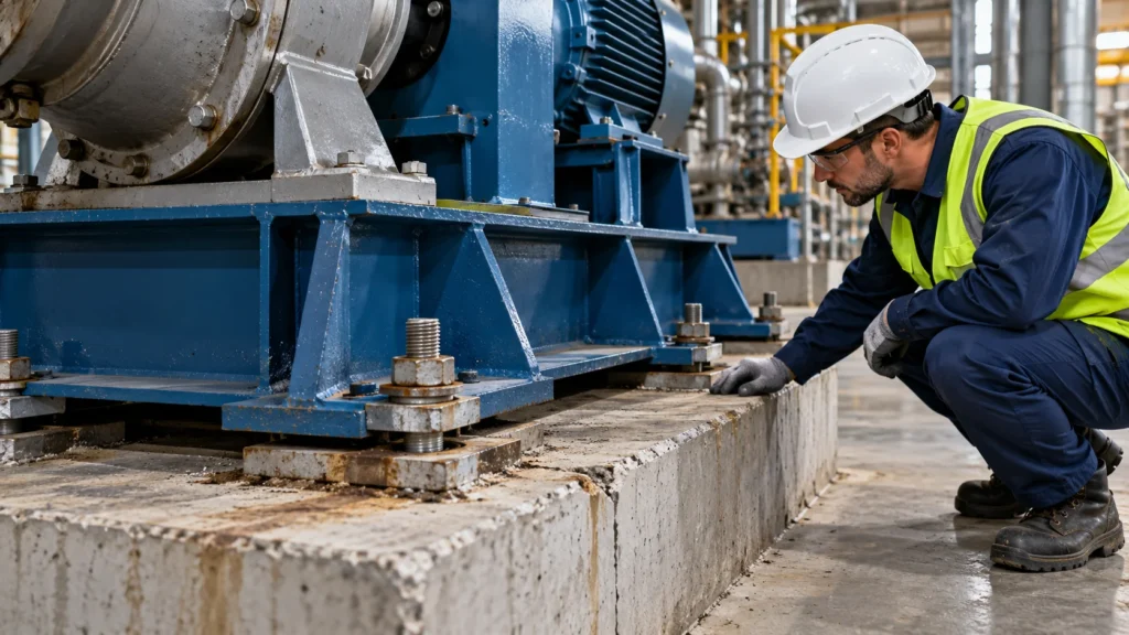
Bearings support rotating components, and their operating condition directly affects mechanical stability.
When the bearing raceway, rolling elements, or cage are damaged, periodic impacts and abnormal vibrations may occur.
Insufficient lubrication, contaminated grease, incorrect lubrication methods, improper installation, and overloading can all accelerate bearing failure.
Common Symptoms:
- The machine emits a persistent humming, grinding, or irregular knocking sound.
- Increased vibration near the bearing.
- Abnormally high bearing temperatures.
- Changes in high-frequency vibration characteristics.
However, an increase in bearing temperature does not necessarily indicate bearing failure; it may also be related to lubrication, load, ambient temperature, or other mechanical issues.
Solution:
Check the bearing’s lubrication status, seal condition, and equipment load conditions. If necessary, perform a diagnosis using vibration spectra, envelope analysis, and bearing characteristic frequencies.
Once bearing damage is confirmed, replace the bearing in accordance with equipment maintenance specifications and investigate the root cause of the premature bearing failure.
If the root cause is shaft misalignment or rotor imbalance, similar failures may recur even after replacing the bearings.
Mechanical Looseness
When bolts, bearing housings, connecting components, or mounting brackets on a machine become loose, the overall stiffness of the equipment and the force transmission path may change.
As a result, vibrations that were originally minor may be amplified.
Mechanical looseness can sometimes produce knocking, clattering, or irregular vibrations, and the fault may worsen as the load changes.
Solution:
Inspect the equipment’s mounting bolts, bearing housings, frame connections, and other critical fastening points.
If looseness is detected, verify whether the threads, mating surfaces, or related parts are damaged, and repair them according to the manufacturer’s specified tightening procedures and torque values.
For locations where loosening recurs, further inspection should be conducted to determine whether structural deformation, improper installation, or persistent abnormal dynamic loads are present.
Simply retightening bolts repeatedly without addressing the root cause of the loosening usually fails to resolve the issue in the long term.
Unstable or Improperly Installed Equipment Foundation
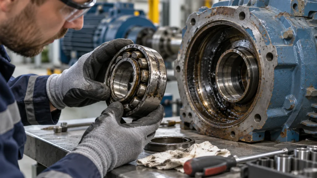
Sometimes vibration does not originate from within the equipment but is amplified by problems with the base, foundation, or support structure.
For example, if the motor mounting feet do not fully contact the mounting surface, a so-called “soft foot” problem may occur.
When the mounting bolts are tightened, the machine base may deform, which in turn affects bearing loads or shaft alignment.
Other common issues include insufficient foundation stiffness, cracks in support components, base deformation, and improper equipment placement.
Solution:
Inspect the contact conditions of each mounting foot, the flatness of the support surface, and the structural integrity of the base.
For equipment with soft foot issues, measurements should be taken and corrections made in accordance with professional alignment and installation procedures.
If cracks in the foundation, damage to the support structure, or significant deformation are found, a structural assessment should be conducted first to determine the appropriate repair or reinforcement plan.
Additionally, when external piping imposes significant additional loads on the equipment, inspect the piping supports and connection methods to prevent the transfer of piping stresses to the equipment housing.
Mechanical Resonance
Why do some machines run smoothly at low speeds but suddenly vibrate violently once the speed increases beyond a certain range?
One possible cause is structural resonance.
Every mechanical system has its own natural frequency. When the frequency of an external excitation approaches a particular natural frequency, the system may exhibit a significant vibrational response.
Here’s a simple example:
Suppose a rotating machine operates at 1,500 r/min, with a rotational frequency of 25 Hz per revolution. If the mechanical structure has a pronounced resonance mode near this frequency, it may amplify vibrations related to the rotational speed.
The 25 Hz mentioned here is only the rotational fundamental frequency. Actual equipment may also exhibit harmonics, gear meshing frequencies, and other excitation frequencies; therefore, resonance cannot be determined based solely on rotational speed.
Solution:
First, confirm whether the abnormal vibration is concentrated within a specific speed range, then identify relevant structural characteristics through vibration testing, speed-sweep analysis, or modal analysis.
Based on the diagnostic results, the following measures can be taken:
- Adjust the equipment’s operating speed to avoid prolonged operation within severe resonance zones.
- Optimize the support structure to increase or appropriately adjust the system’s stiffness.
- Adjust the system’s mass distribution after calculation and verification.
- Reduce resonance peaks through appropriate damping measures.
- Design a suitable elastic support system for equipment requiring vibration isolation.
Note that adding rubber pads does not necessarily eliminate resonance. If the new supports alter the system’s natural frequency, they may actually make the vibration problem more pronounced.
Abnormalities in Gears, Belts, and Transmission Components
Industrial machinery typically relies on gears, belts, chains, or other mechanical transmission devices to transmit power.
If transmission components experience wear, assembly deviations, or improper tension, the equipment may exhibit additional vibration and noise.
For example, excessive belt tension may increase bearing loads, while insufficient tension may lead to slippage or abnormal dynamic responses.
Poor gear meshing, tooth surface damage, and abnormalities in drive shafts can also generate vibrations with specific frequency characteristics.
Solution:
Inspect the transmission components for wear, installation alignment, lubrication conditions, and tension.
For gearboxes, conduct further analysis by considering the gear meshing frequency and its side-band characteristics.
For belt drive systems, tensioning and alignment should be performed according to equipment requirements; simply increasing tension will not eliminate all vibrations.
Electrical Vibration
Mechanical vibration does not necessarily originate entirely from mechanical components.
For electric motors, power supply abnormalities, changes in electromagnetic forces, rotor electrical faults, or other electromagnetic issues can all cause periodic vibrations.
In some cases, even if there are no obvious problems with the bearings or mechanical connections, the motor may still exhibit abnormal noise and vibration.
The characteristics of electromagnetic vibration and mechanical vibration may overlap, requiring a comprehensive assessment that combines electrical measurements and mechanical vibration data.
Solution:
Have a qualified electrical maintenance technician inspect the power supply voltage, current, phase balance, and relevant motor operating parameters.
If necessary, analyze the source of the problem by combining current spectrum and mechanical vibration spectrum analyses.
Do not attempt to resolve suspected electromagnetic faults by simply replacing bearings or adding vibration-damping pads before the cause has been determined.
Fluid Turbulence, Pump Cavitation, and Pressure Pulsations
For centrifugal pumps, hydraulic equipment, and other fluid machinery, abnormal vibrations may originate from the internal fluid state, not just the mechanical structure.
Taking centrifugal pumps as an example, when inlet conditions do not meet requirements, local liquid pressure may drop and form bubbles. When these bubbles collapse in areas of higher pressure, they can generate shock waves, noise, and vibration—a phenomenon known as cavitation.
In addition, flow deviations from design conditions, pressure pulsations in the piping, and fluid turbulence may also cause equipment vibration.
Common manifestations:
- Abnormal noise during pump operation.
- Equipment vibration varies with changes in flow rate or pressure.
- Vibration accompanied by a decline in operational performance.
- Noticeable vibration transmission in piping and support structures.
Solutions:
Inspect the pump inlet conditions, piping resistance, filter condition, actual flow rate, and equipment operating conditions.
For suspected cavitation issues, verify the available cavitation margin against the pump’s requirements and check for problems such as insufficient suction conditions.
If the problem stems from the fluid system design, simply installing vibration dampers may reduce some structural vibration transmission but cannot directly eliminate cavitation.
Load variations, external shocks, and unreasonable process conditions
The vibration of some industrial equipment is closely related to operating conditions.
For example, CNC machining equipment may experience flutter under specific cutting parameters; reciprocating equipment is subject to periodic inertial loads; and construction machinery may be subjected to impacts from the operating environment.
When equipment operates beyond its design conditions, or when excitation conditions do not match the structural characteristics, vibration may increase significantly.
Solution:
Check whether the actual load on the equipment is within the permissible range, and verify that the operating speed, machining parameters, and duty cycle are appropriate.
For machine tools experiencing cutting flutter, process engineers can adjust the cutting parameters based on the tool, workpiece, and the rigidity and stability of the clamping system.
For equipment subjected to periodic impacts, consider incorporating cushioning, limit stops, and elastic support designs to reduce the impact’s effect on the equipment and surrounding structures.
What to Do When Machine Vibration Is Excessive?
Once you understand the common causes of vibration, the next most important step is to establish the correct troubleshooting sequence.
When faced with abnormal equipment vibration, it is not recommended to replace vibration dampers or disassemble mechanical parts right away. You can organize an inspection by following these steps.
Step 1: Identify the conditions under which the vibration occurs
First, record the time and operating conditions when the problem occurs.
You need to answer a few questions:
- Did the vibration appear suddenly, or did it gradually worsen?
- Is the vibration noticeable during a cold start, or does it become more severe after the equipment has been running for a while?
- Does the vibration intensify as rotational speed or load increases?
- Is the problem only noticeable within a specific speed range?
- Have any bearings, couplings, or other components been replaced recently?
- Does the vibration originate from the equipment itself, or is it primarily transmitted through the floor, piping, and frame?
This information can help narrow down the cause of the fault.
For example, if a piece of equipment begins to exhibit abnormal vibration after a coupling replacement, the installation condition and shaft alignment should be checked first, rather than immediately suspecting damage to the motor rotor.
Step 2: Check for Obvious Mechanical Abnormalities
After safely shutting down the equipment, isolating the relevant power sources, and confirming that the equipment cannot start unexpectedly, have authorized maintenance personnel inspect:
- Installation bolts and connection points.
- Bearings and lubrication conditions.
- Couplings and drive components.
- Equipment bases and support structures.
- Rubber vibration-damping mounts for cracks, permanent deformation, or separation from metal components.
- Piping, limit stops, and other components that may cause rigid contact.
When performing maintenance on industrial equipment, energy isolation and lockout/tagout procedures must be implemented in accordance with applicable safety regulations and company procedures. Do not search for the source of vibration with bare hands near rotating parts.
Step 3: Measure Vibration Using Instruments
If a visual inspection fails to identify a clear cause, a data-driven assessment is required.
Common vibration parameters include:
Displacement
Typically expressed in millimeters or micrometers, this parameter reflects the distance an object deviates from its reference position. The displacement parameter is particularly important for certain low-frequency vibrations or shaft vibration measurements.
Velocity
Typically expressed in mm/s. For many industrial rotating machines, the root mean square (RMS) vibration velocity is a key indicator for assessing the overall vibration condition.
Acceleration
Typically expressed in m/s² or g, it is suitable for analyzing dynamic responses across different frequency ranges. In scenarios such as bearing fault diagnosis, high-frequency acceleration and its signal processing results provide important reference value.
These three parameters cannot be directly compared without considering the measurement frequency, method, and equipment type.
For equipment such as motors, fans, and pumps, it is typically necessary to measure horizontal, vertical, and axial vibration at appropriate bearing housings or designated measurement points, while recording rotational speed, load, and operating conditions.
Step 4: Perform Vibration Spectrum Analysis
Vibration analysis can help you further identify the frequency composition of abnormal vibrations.
For example, when strong vibration components appear near the rotational frequency, it may be necessary to investigate issues such as imbalance; when abnormal axial vibration or specific harmonic features appear, it may be necessary to further inspect misalignment and the condition of mechanical connections.
However, these are merely diagnostic clues.
One cannot simply assume that the presence of the 1× rotational frequency indicates imbalance, or that the presence of the 2× rotational frequency indicates misalignment.
A correct diagnosis usually requires a combination of phase, vibration direction, historical trends, machine structure, and other operational information.
For equipment with suspected bearing damage, methods such as high-frequency analysis or envelope analysis may also be required.
Step 5: Confirm the Cause of the Failure and Verify the Effectiveness of Repairs
After completing the diagnosis, repairs or adjustments should be made to address the root cause.
If the problem stems from rotor imbalance, perform the appropriate balancing correction; if it stems from shaft misalignment, perform an alignment adjustment; if it stems from an inappropriate vibration isolation system, reevaluate the support configuration.
After repairs, remeasurements should be taken at the same measurement points, at the same rotational speed, and under similar load conditions to confirm whether the vibration has improved significantly.
Record the data both before and after repairs to establish a baseline for future condition monitoring.
How can machine vibration be reduced?
There is no single technical approach to solving machine vibration problems.
From an engineering perspective, measures can be divided into three levels: reducing excitation sources, controlling vibration propagation, and improving structural response.
Reducing excitation generated by the vibration source
This is the top priority.
For example, improving rotor dynamic balancing, correcting shaft alignment, replacing damaged bearings, optimizing lubrication conditions, or adjusting improper operating conditions.
These methods address the root causes of abnormal vibration.
If the equipment has already exhibited clear mechanical failures, the failure should be addressed first, and only then should the need for additional vibration isolation measures be considered.
Reducing vibration transmission using vibration isolation systems
Even when mechanical equipment is operating normally, rotational, reciprocating, and periodic loads can still generate vibrations that cannot be completely eliminated.
In such cases, vibration isolation is typically an effective engineering measure.
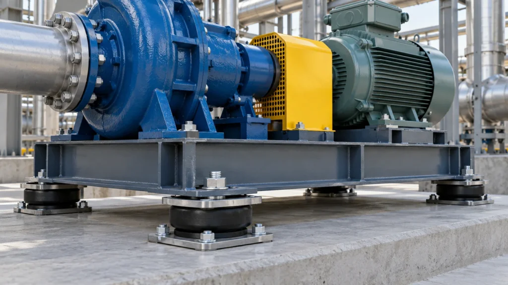
The goal of a vibration isolation system is to establish an appropriate elastic connection between the equipment and its foundation, frame, or other protected structure, thereby reducing vibration transmission within a specific frequency range.
Common vibration isolation products used in industrial equipment include:
- Rubber Anti-Vibration Mounts
- Machine Feet
- Rubber-Metal Mounts
- Rubber Isolation Pads
- Spring isolators and other elastic support devices for specific operating conditions
Rubber possesses viscoelastic properties, providing both support and elastic recovery while dissipating some energy during deformation.
However, the performance of different vibration isolators varies significantly; one cannot assume that a product will necessarily provide sufficient vibration damping simply because it uses rubber.
Optimizing Mechanical Structures and Damping
For equipment exhibiting significant resonance or localized structural vibrations, one may also consider adjusting structural stiffness, optimizing support locations, or implementing design-verified damping measures.
However, structural reinforcement does not always guarantee a reduction in vibration.
If changes in stiffness cause the natural frequency to approach the equipment’s primary excitation frequency, vibration may actually increase under certain operating conditions.
Therefore, frequency characteristics, load paths, and actual operating conditions should be considered before making structural adjustments.
How to Select Vibration Dampers for Industrial Machinery?
Once it has been confirmed that vibration transmission needs to be controlled, the next step is to select the appropriate vibration isolation components.
For industrial procurement personnel and equipment design engineers, the selection of vibration isolators should not be based solely on dimensions, rubber hardness, or the total weight of the equipment.
Determine the Equipment Weight and Load at Support Points
First, you need to understand the equipment’s total weight, center of gravity, number of support points, and installation layout.
For example, even if a piece of equipment uses four vibration isolators, if the motor and gearbox are concentrated on one side, the actual loads borne by the four support points may vary significantly.
It cannot be directly assumed that each support point bears one-fourth of the equipment’s weight.
Proper selection should be based on the load at each support point, any eccentricity, and the dynamic forces acting on the equipment.
Determine the operating frequency and natural frequency
Vibration isolation performance is closely related to the excitation frequency and the natural frequency of the isolation system.
A frequency ratio is typically used for preliminary analysis:
Frequency ratio r = excitation frequency / system natural frequency
In commonly used single-degree-of-freedom linear vibration isolation models, significant resonance may occur when the excitation frequency approaches the system’s natural frequency.
However, the system can only demonstrate effective vibration isolation when the frequency ratio falls within an appropriate range.
In actual engineering applications, factors such as damping, multiple vibration directions, the equipment’s center of gravity, and the dynamic stiffness of the rubber must also be considered.
In particular, for equipment operating at variable frequencies, vibration isolators should not be selected based solely on the rated speed; attention must also be paid to whether the minimum operating speed, as well as the start-up and shutdown phases, pass through unfavorable resonance regions.
Selecting the Structure Based on Load Direction
Industrial vibration isolators may primarily bear compressive, shear, tensile, or combined loads.
For example, certain machine feet are primarily used to bear vertical loads, while engine mounts may need to control vertical, lateral, and longitudinal displacements simultaneously.
Different structures have varying stiffness, allowable deformation, shock resistance, and limiting capabilities.
If the equipment is also subject to overturning moments or significant transient impacts, dynamic displacement and anti-detachment requirements should be comprehensively considered; verification should not be limited to static load-bearing capacity alone.
Selecting Rubber Materials Based on the Operating Environment
The performance of rubber vibration isolators depends not only on their structure but is also influenced by material formulations and environmental conditions.
Common engineering materials include:
Natural rubber (NR): Possesses good elasticity and can be used for vibration isolation in suitable environments, but caution is required when in contact with certain oil-based media.
Nitrile rubber (NBR): Generally offers good resistance to petroleum-based oils and is suitable for certain applications where contact with lubricating oil or hydraulic oil may occur.
Ethylene Propylene Diene Monomer (EPDM): Generally offers good ozone and weather resistance, but is typically not suitable for environments involving long-term exposure to petroleum-based oils.
Chloroprene Rubber (CR): Offers a certain degree of weather resistance and can be used in some applications requiring both environmental adaptability and elasticity.
Silicone Rubber: Offers advantages in certain applications with specific temperature requirements, but mechanical strength and durability must still be verified.
Material selection cannot be based solely on the material name; it must be verified in conjunction with the formulation, operating temperature, contact media, stress conditions, and service life requirements.
Verification of Dynamic Performance and Installation Conditions
The fact that a vibration isolator can support the weight of equipment does not necessarily mean it will provide ideal vibration isolation performance.
Especially for rubber components, dynamic stiffness may differ significantly from static stiffness.
If the vibration damping effect is estimated based solely on rubber hardness or static compression, the actual operating results may deviate from the design objectives.
When selecting a model, attention should be paid to the load-displacement curve, dynamic stiffness, allowable displacement, vibration isolation performance at relevant frequencies, and necessary durability tests.
After installation, it is also necessary to check for any rigid connections that bypass the vibration isolator.
For example, piping that is too tight or lacks a flexible design, or limiters in direct contact with the frame, can create vibration transmission paths and reduce vibration isolation effectiveness.
Engineers seeking further guidance on product selection can refer to Vista Motion’s Industrial Vibration Isolation Mount Selection Guide.
How should vibration control solutions be developed for different types of industrial equipment?
Although vibration issues in various types of industrial machinery share commonalities, specific solutions must still be tailored to the equipment’s structure.
Motors and Generators
When investigating motor vibration, priority should be given to examining rotor balance, bearing condition, alignment accuracy, base stiffness, and electromagnetic factors.
If the equipment itself is operating normally but vibration is clearly transmitted to the frame or building structure, the machine’s vibration-isolation feet, elastic mounts, and their mounting systems should be further evaluated.
For units where a motor is installed together with other equipment, the connection stiffness between the two components and the requirements for relative displacement should be considered simultaneously.
Pumps and Compressors
In addition to mechanical failures, pumps and compressors may also be affected by fluid pulsations, piping forces, and variations in operating loads.
The vibration isolation design for such equipment must not only consider the weight of the main unit but also evaluate piping connections, equipment start-up and shutdown, and dynamic loads.
Industrial Fans
For fans, special attention should be paid to impeller cleanliness, rotor dynamic balance, bearing condition, and installation stiffness.
For fans that transmit noticeable vibrations to the frame or foundation even during normal operation, appropriate flexible supports may be considered, provided that the equipment’s installation stability and safety requirements are ensured.
Construction Machinery and Mobile Equipment
Construction machinery is often subjected to engine vibrations, road impacts, and operational loads simultaneously.
Such applications not only require reduced vibration transmission but also demand control of equipment displacement and reliable connections under impact and complex loading conditions.
Therefore, the design of engine vibration isolation mounts, cab suspensions, and other rubber-metal composite components must balance vibration isolation, load-bearing capacity, position limiting, and durability.
Precision Equipment and Automated Machinery
Precision equipment may have high requirements for external vibration and its own dynamic stability.
For this type of equipment, a comprehensive assessment of operating frequency, allowable displacement, mounting foundation, and ambient vibration levels should be conducted.
If low-frequency vibration isolation requirements are very high, ordinary rubber mounts may not be sufficient, and a more suitable vibration isolation system may be needed.
The key to selecting a vibration isolation solution is not to find the softest material, but to strike a reasonable balance between load-bearing capacity, vibration isolation performance, displacement control, and service life.
Why does vibration still occur after installing machine vibration isolators?
Some equipment already uses rubber vibration-isolation mounts, yet vibration problems remain significant—and in some cases, are even more severe than before installation.
This situation cannot be directly attributed to a defect in the shock absorber.
The reasons may include the following.
First, the shock absorber’s stiffness is too high. If the system’s natural frequency is too high, the equipment’s actual operating frequency may be insufficient to provide effective vibration isolation.
Second, the damper stiffness is too low or the support layout is unreasonable. This may result in excessive equipment displacement, noticeable swaying, or even collisions with surrounding structures.
Third, the load distribution at the support points is uneven. Some supports may be subjected to long-term overloading, resulting in excessive compressive deformation, while other supports may not be fully engaged in the load-bearing process.
Fourth, the installation includes rigid connections. Even if the vibration isolation bearings perform well, piping, brackets, and other rigid connections may still allow vibrations to bypass the isolation system and be transmitted.
Fifth, the rubber material has aged or become damaged. Prolonged exposure to temperature, oils, ozone, and repeated loading may cause the rubber to crack, harden, undergo permanent deformation, or fail to bond properly to the metal.
If abnormalities occur after installing vibration isolators on equipment, it is recommended to re-inspect the entire support system rather than simply replacing the rubber pads with a different type.
How can you determine whether a machine’s vibration isolation measures are truly effective?
Vibration reduction effectiveness cannot be determined solely by subjective perception.
A more reliable method is to establish clear measurement criteria and compare results before and after implementing measures.
We recommend evaluating the effectiveness based on three aspects.
Is the vibration of the equipment itself within the permissible range?
Check the vibration levels at the bearing housings, machine casing, or manufacturer-specified measurement points to confirm that the vibration isolation measures are not masking serious mechanical failures.
If necessary, conduct an assessment in accordance with applicable standards and manufacturer requirements.
Has the degree of vibration transmission to the outside been reduced?
If the goal is to isolate vibrations transmitted from the equipment to the foundation, attention should be paid to the response on both sides of the equipment and the foundation.
If the goal is to protect precision equipment, attention should be paid to the actual vibration behavior of the equipment being protected.
Do not assume that the vibration isolation objective has been achieved simply because vibration isolators have been installed.
Is long-term operation stable?
Low vibration levels during initial installation do not guarantee reliable long-term operation.
It is still necessary to monitor rubber deformation, material aging, the condition of fasteners, temperature changes, and equipment operating conditions.
Establishing a schedule for regular inspections and recording vibration trends can help maintenance personnel detect abnormal changes earlier.
Summary
Machine vibration does not always indicate a malfunction, but an abnormal increase in vibration should not be ignored.
For issues such as rotor imbalance, shaft misalignment, bearing damage, and mechanical looseness, priority should be given to identifying the root cause and performing repairs. For vibrations that are unavoidable during normal equipment operation, the transmission of vibrations to the foundation, frame, and surrounding structures can be reduced through proper elastic support and vibration isolation design.
A truly effective machine vibration isolation solution is not simply adding a piece of rubber, but rather ensuring that the vibration isolator’s load-bearing capacity, stiffness, damping, structural configuration, and equipment operating conditions are properly matched.
If you are seeking reliable vibration control solutions for motors, pumps, compressors, construction machinery, or other industrial equipment, Vista Motion can provide you with a range of products—including industrial rubber vibration isolators, machine vibration mounts, engine mounts, and customized rubber-to-metal vibration control components—along with technical support.
Whether you are developing new equipment or looking to optimize the vibration isolation structure of existing machinery, you can contact us through the Vista Motion contact page to discuss your specific needs and work together to develop a vibration control solution best suited to your actual operating conditions.
FAQ
What are the main causes of machine vibration?
The most common mechanical causes include rotor imbalance, shaft misalignment, bearing wear, and mechanical looseness. In addition, insufficient foundation stiffness, structural resonance, transmission failures, fluid disturbances, and electromagnetic issues with motors can also cause abnormal vibrations.
If the machine has recently undergone repairs or had parts replaced, you should prioritize checking for related installation changes. An accurate diagnosis requires a combination of vibration data, equipment structure, and operating conditions—not just a judgment based on sound alone.
What should be done if machine vibration is excessive?
First, confirm whether there are any risks to personnel safety. If the equipment exhibits sudden, violent vibration, abnormal impacts, severe overheating, or signs of structural damage, shut down the machine and inspect it in accordance with safety procedures.
Next, record the rotational speed, load, time of the fault occurrence, and location of the vibration, and inspect the condition of the bearings, couplings, mounting bolts, and base.
If the cause cannot be determined, use vibration measurement instruments to conduct tests, and have a professional develop a repair plan based on the analysis results. Do not attempt to diagnose the problem simply by installing thicker rubber pads.
What are the causes of excessive motor vibration?
Common causes of excessive motor vibration include rotor imbalance, bearing damage, shaft misalignment, loose motor mounting, and electromagnetic abnormalities.
If the motor vibrates noticeably even when unloaded, focus the inspection on the motor itself and its mounting system; if vibration increases significantly after connecting a load, also inspect the coupling, driven equipment, and load conditions.
If necessary, conduct separate mechanical vibration measurements and electrical condition inspections.
What causes excessive vibration in a water pump?
Vibration in a water pump may result from impeller imbalance, bearing failure, shaft misalignment, loose mounting, or foundation resonance.
If the vibration is clearly related to changes in flow rate or pressure, cavitation, inadequate suction conditions, and other hydraulic issues should also be investigated.
The correct approach is to inspect both the mechanical system and the fluid operating conditions simultaneously, rather than simply replacing bearings or vibration dampers.
Can bearing damage cause machine vibration?
Yes. Damage to the raceways, rolling elements, or cages can cause impact and characteristic vibrations.
However, increased vibration does not necessarily indicate bearing damage. Improper lubrication, misalignment, and load variations can also produce similar symptoms.
For critical equipment, it is recommended to make a determination by combining bearing natural frequencies, vibration trends, and appropriate signal analysis methods to avoid unnecessary component replacement.
How is machine vibration detected? What instruments are required?
Common instruments include vibration meters, accelerometers, vibration analyzers, and online condition monitoring systems.
Basic testing typically focuses on the magnitude of vibration velocity, acceleration, or displacement; when fault diagnosis is required, further analysis of the vibration spectrum, phase, and time waveforms can be performed.
When selecting instruments, consider the equipment’s rotational speed, frequency range, measurement location, and the purpose of the inspection. For critical equipment operating continuously over the long term, establishing periodic or online vibration monitoring is generally more beneficial for trend analysis.
What vibration levels are considered normal for machinery?
There is no single standard for normal vibration levels that applies to all industrial machinery.
Whether vibration is acceptable must be determined based on the equipment type, rated power, rotational speed, support method, measurement location, and specific applicable standards.
For example, the ISO 20816 series covers the measurement and evaluation of machine vibration, but different equipment requires reference to the specific applicable sections; a single vibration velocity value cannot be directly treated as a safety threshold for all machines.
For actual equipment, priority should be given to the permissible values specified by the manufacturer, and evaluations should be conducted in conjunction with historical baselines and operating conditions.
Why does the machine vibrate particularly heavily at a certain rotational speed?
This phenomenon may be related to mechanical resonance.
When a certain excitation frequency of the equipment approaches the structure’s natural frequency, the vibration response may increase significantly, causing the machine to exhibit noticeable shaking within a specific speed range.
However, speed-related vibration may also stem from issues such as rotor imbalance.
It is recommended to record the trend of vibration as a function of speed and to distinguish the cause through necessary spectral, phase, or modal analysis. For confirmed resonance issues, adjustments can be made to operating speed, structural stiffness, damping, or the design of the vibration isolation system based on the specific circumstances.
What is the difference between rubber vibration-damping pads and industrial vibration isolators?
Rubber vibration isolation pads typically have a relatively simple structure and primarily provide support and vibration isolation through elastic materials.
Industrial vibration isolators or mounts, on the other hand, may employ a composite structure of rubber and metal and are designed for specific load directions, mounting methods, allowable displacement, and dynamic performance.
The two are not entirely distinct product categories, and there is some overlap in their actual functions.
If the equipment is heavy, subject to complex forces, or requires strict control of displacement and vibration transmission, vibration isolation products with clearly defined performance data should be selected based on engineering parameters, rather than judging solely by name or price.
Why does the machine vibrate more after installing rubber vibration isolators?
It may be that the vibration isolator is not suited to the equipment’s operating conditions.
For example, inappropriate support stiffness, load distribution, or installation methods may cause the system to enter a frequency range where vibrations are amplified; excessive equipment displacement may also cause additional swaying or collisions.
Furthermore, if vibrations bypass the vibration isolators and propagate through rigid pipes, brackets, or other pathways, this will also affect the vibration isolation performance.
We recommend checking the actual support load, static compression deformation, operating frequency, dynamic stiffness, and installation connections, and comparing vibration data on both sides of the equipment and foundation before deciding whether to select a different model.
