
Railway air suspension systems have developed alongside the vehicles they support. Early applications established the value of pneumatic springing and load compensation. Subsequent work addressed more demanding bogie movements, vehicle-specific tilt functions and ways to detect suspension faults. Research into controlled damping has added further possibilities for managing ride quality.
For engineers and procurement teams, this history offers a practical lesson: assess an air spring in the context of the vehicle, its air circuit and its required operating behaviour. The following guide focuses on passenger rolling stock and connects documented developments with the questions that matter when specifying components today.
What Does a Railway Air Suspension System Include?
Primary vs. Secondary Suspension
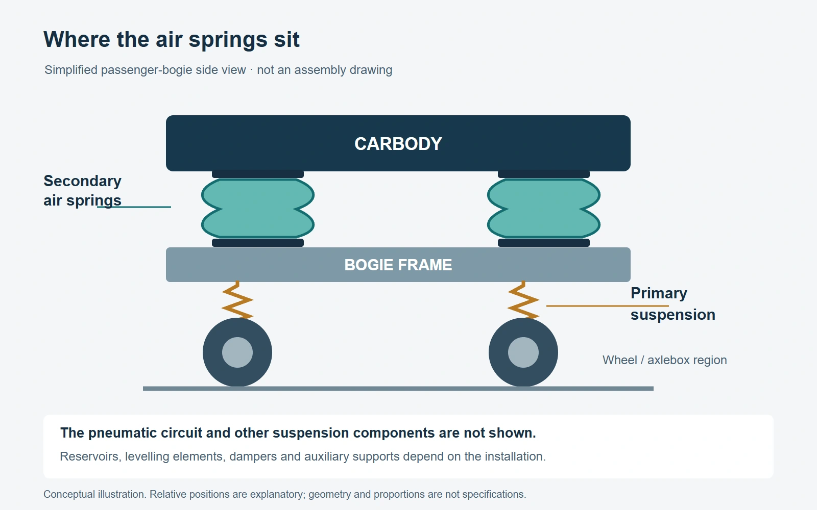
A typical passenger bogie—also called a truck in North American terminology—has primary suspension between the wheelset/axlebox arrangement and the bogie frame, and secondary suspension between the bogie and carbody. Railway air springs commonly serve this secondary stage. Sumitomo Electric's technical history describes this arrangement and its development in Shinkansen vehicles.
The distinction matters when discussing railway suspension components: a specification should identify both the component and its position in the vehicle.
The Air Spring and Its Supporting Components
An air spring uses compressed air as an elastic medium. The flexible diaphragm and its fittings contain that air while allowing movement. Connecting the spring to an appropriate air-control arrangement enables functions such as height adjustment. Nitta's railway air-spring description explains these basic functions.
The complete installation has a wider boundary than the flexible element alone. For procurement, separate the following items in the request:
| Item to identify | Question for the supplier or system integrator |
|---|---|
| Diaphragm and assembled air spring | Exactly which parts and interfaces are included? |
| Air reservoir and connecting circuit | Which pneumatic arrangement was used to establish performance? |
| Levelling and other control elements | Who supplies, configures and validates them? |
| Auxiliary or emergency support | Which assembly and operating condition does the evidence cover? |
| Other suspension components | Who verifies compatibility with dampers, restraints and the bogie? |
This separation is reflected in ISO 18955:2025, whose scope concerns suspension diaphragms and explicitly excludes several other air-suspension and control-system components. A quotation for a diaphragm should therefore never be read as a quotation for the entire installation.
Why Did Rail Vehicles Adopt Air Springs?
Air suspension offered designers a useful combination: compliant support and a means of regulating vehicle height as loading changed. Contemporary railway products still emphasise these functions. For example, Wabtec describes its air-spring system as maintaining carbody height under varying loads and combining an air bellows with an emergency spring.
Early Applications and the Move into High-Speed Rail
Nitta records the start of its air-spring research in 1954 and its involvement in the first-generation Shinkansen in 1964. These are documented company milestones, rather than a claim about the world's first railway air spring. Source: Nitta.
Later developments illustrate how the engineering task broadened:
| Selected milestone | Development documented by the source |
|---|---|
| 1954 | Nitta began researching air springs. |
| 1964 | Nitta participated in air-spring development for the first-generation Shinkansen. |
| 2007 | The N700 entered service with an air-spring-based carbody tilting arrangement. |
| 2013 | RTRI reported experimental work on detecting air-spring deflation through bogie vibration. |
| 2024 research results | RTRI described a combined primary and secondary vertical semi-active damping system. |
Sources: Nitta, Sumitomo Electric, RTRI's 2013 newsletter and RTRI's 2024 research summary. These examples trace selected developments in Japan; they are not a complete chronology of worldwide adoption.
Read the milestones as responses to different engineering problems. When evaluating a present-day proposal, ask which problem its additional functions solve for your vehicle and what evidence supports that benefit.
How Did Bogie Design Change Air-Spring Requirements?
From Vertical Support to Multidirectional Movement
Changes in bogie construction expanded the demands placed on air springs. Sumitomo's account of Shinkansen development describes the need to accommodate lateral behaviour and the movement associated with bolsterless bogies. This made the spring's response in several directions relevant to its design. Source: Sumitomo Electric.
Product geometry also reflects the installation. Continental, for example, describes half-bellows designs for substantial lateral movement and rolling-lobe designs for restricted installation spaces. These are examples from its own portfolio, not a universal selection rule. Source: Continental.
For a replacement project, treat physical fit as the beginning of the comparison. Ask the engineering team to review the proposed part against the original functional requirements before treating matching dimensions as evidence of interchangeability.
The following table translates the development themes into practical review questions:
| Design consideration | Trade-off to investigate | Evidence to request |
|---|---|---|
| Greater relative movement | Available travel versus packaging constraints | Interface drawing and permitted movement envelope |
| Required lateral response | Displacement allowance versus restoring behaviour | Relevant force–displacement data and test conditions |
| Pneumatic integration | Packaging choices versus required dynamic response | Circuit definition and test configuration |
| Additional control functions | Intended benefit versus integration and maintenance needs | Functional description, validation plan and fault response |
Use the table to assign responsibility. A component supplier may provide part data, while the vehicle engineer remains responsible for deciding whether those data satisfy the installation's requirements.
How Did Levelling and Pneumatic Tuning Expand the System's Role?
Reservoirs, Restrictions and Suspension Response
Air-spring behaviour depends on more than the rubber element. A published experimental and modelling study of a railway air-spring system examined the effects of diaphragm volume, auxiliary-chamber volume and connecting restriction. It found that the measured response depended on the configuration and excitation conditions. Its numerical results apply to the studied system, rather than providing universal design settings. Source: Xu, 2020.
This makes the test arrangement an important part of a specification. When reviewing a stiffness curve, ask for the load, installed height, chamber arrangement and excitation conditions behind it. If two quotations use different configurations, request a comparison on an agreed basis before drawing a performance conclusion.
Levelling and Vehicle-Specific Tilt Functions
A levelling valve admits or releases air to regulate spring height as loading changes. Some vehicle designs give the air suspension additional tasks: the N700 example used unequal air-spring extension for carbody tilt. Both functions are discussed in Sumitomo's technical paper.
For a project review, keep three questions separate: what determines the spring's dynamic response, what regulates the normal ride height, and whether a specific tilt function is required. Ask the supplier to identify each function in the architecture and state how it is verified.
Height regulation alone is insufficient evidence for a claim about vibration-control performance. Request the relevant ride-response assessment whenever that benefit is part of the proposal.
What Do Monitoring and Active Control Add?
Fault Detection Is Different from Active Ride Control
Monitoring helps establish the condition of the suspension. RTRI reported tests that distinguished an inflated air spring from a deflated one using changes in bogie-frame vibration. The report describes an experimental detection method; it does not establish a universal diagnostic threshold for every vehicle. Source: RTRI, April 2013.
Controlled suspension performs another task. RTRI's 2024 work combined variable primary and secondary vertical dampers, with the aim of improving vertical ride comfort while reducing implementation cost. A separate 2018 study described adding a vertical actuator between the bogie and carbody to extend vibration control. These examples concern the wider suspension arrangement, rather than a sensor turning an air spring into an active system. Sources: RTRI 2024 and RTRI 2018.
For procurement, replace a broad label such as “smart suspension” with a functional description:
- Monitoring: which condition is detected, and how is the result communicated?
- Levelling: which height is regulated, under what loading conditions?
- Controlled damping: which damper characteristics can change?
- Actuator-based control: which movement is controlled, and what supporting equipment is required?
For each proposed function, request its demonstrated operating range, integration requirements and behaviour when a sensor or control element becomes unavailable. Compare proposals against the same vehicle requirement rather than the number of electronic features listed.
Which Risks Remain as Systems Become More Capable?
Normal Performance and Degraded Conditions Need Separate Evidence
Air loss deserves explicit attention. RTRI's deflation-detection work explains that damaged bellows or leaking pipework can change the support condition and vehicle response. Its findings reinforce the need to assess a deflated condition separately from normal operation. Source: RTRI.
An emergency spring is a component of some assemblies, including the Wabtec system described earlier. Its presence should prompt a request for the relevant vehicle assessment; it is not, by itself, permission to continue normal service.
Build the following questions into the technical review:
- Which failure conditions have been considered for this installation?
- What evidence addresses the specified load and movement in each condition?
- How will a relevant fault be detected and communicated?
- Which vehicle documents define the permitted response and maintenance action?
Keep operating limits and inspection intervals tied to the applicable vehicle and operator documentation. Generic article guidance cannot establish them for an unidentified fleet.
For supplier evaluation, distinguish a description of the design and verification process from the actual reports required for your project. Request the configuration, method, acceptance criteria and recorded result behind each relevant claim. This gives procurement a concrete basis for comparing evidence without substituting a marketing statement for engineering acceptance.
What Should Buyers Validate for Their Vehicle and Operating Market?
Component Evidence vs. Vehicle-Level Validation
Match each document to the item it covers. ISO 18955:2025 specifies characteristics and verification methods for rubber diaphragms used in pneumatic suspension springs. Its published scope excludes components such as reservoirs, piping, levelling systems and emergency suspension systems. It therefore cannot, on its own, establish that a complete vehicle installation is suitable. Source: ISO.
Testing also needs a defined purpose. MTS lists stiffness, multi-axis response, damping measurement and durability among the applications of its rail air-spring test equipment. These categories help frame an evidence request; the equipment description does not set your project's acceptance limits. Source: MTS.
Organise the evidence package into four parts:
- Identification: part number, drawing revision, materials and assembly configuration.
- Performance: agreed load cases, displacement conditions and relevant response data.
- Verification: test method, acceptance criteria, report identity and any stated exclusions.
- Integration: confirmation that the component evidence has been assessed for the specified vehicle arrangement.
Record unresolved items as questions with an owner and due date. This is more useful during supplier selection than a general request to provide “all certificates”.
Turn Regional Conditions into Project Requirements
Use the intended operating market to organise questions, then obtain the actual requirements from the project team. The following are specification prompts, not a country-by-country statement of mandatory rules.
| Market | Inputs to clarify before supplier selection |
|---|---|
| Western Europe | Vehicle and operator specifications, installation interfaces, documentation and applicable acceptance requirements |
| Nordic countries | Route-specific temperature conditions, snow and ice exposure, air-quality requirements and maintenance arrangements |
| Russia | Vehicle configuration, environmental profile, required technical documentation and project acceptance route |
| United States | Vehicle and service category, operator specifications, interface terminology and applicable acceptance requirements |
Apply the same questions wherever the operating conditions make them relevant. A cold-weather requirement should include the specified condition and evidence expected, rather than rely on a phrase such as “suitable for harsh climates”. Likewise, a standard reference should identify the edition and the part or assembly covered.
What Information Should a Railway Suspension RFQ Include?
An effective RFQ connects the required component to its application and verification needs. Prepare the following information before requesting a project assessment:
- Vehicle and purpose: fleet or vehicle type, installation position, new design or replacement, and the responsible engineering contact.
- Drawing and scope: current drawing revision, interfaces and the exact parts or assembly to be supplied.
- Operating requirements: load cases, installed height, required travel and movement envelope, with units clearly stated.
- System interfaces: pneumatic arrangement, relevant control functions and responsibilities for integration.
- Environment: project-defined temperature and exposure conditions, storage requirements and other relevant restrictions.
- Acceptance evidence: applicable specifications, agreed test requirements, documentation and traceability expectations.
- Commercial context: prototype or production quantities, milestones and the requested delivery schedule.
Where information is unavailable, identify who will supply it and whether it is needed before feasibility review, quotation or final acceptance. Keep assumptions visible in the exchange so that later revisions can be assessed against an agreed starting point.
To discuss a custom suspension-component project with Vista Motion, submit your drawings and requirements for a project-specific feasibility review and quotation. Include the application and required verification scope so that the discussion starts with the engineering information that matters.
