This article addresses the control of “structurally transmitted vibration/noise” in common industrial equipment such as pumps, wind turbine, motors, compressors, enclosures, and equipment bases. It focuses on passive vibration isolation components including rubber isolators, rubber damping pads, and rubber-metal vibration dampers.Engineering selection should ultimately be based on supplier load-deflection curves, dynamic stiffness data, and field validation. Estimating solely from static deflection may yield overly optimistic results, particularly for rubber materials.
Why Rubber Effectively Resists Vibration
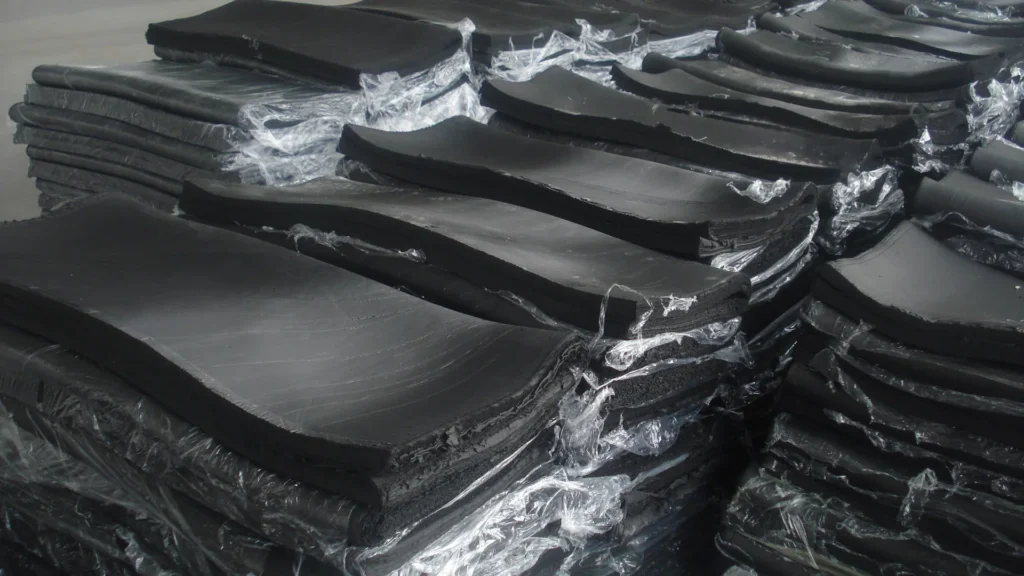
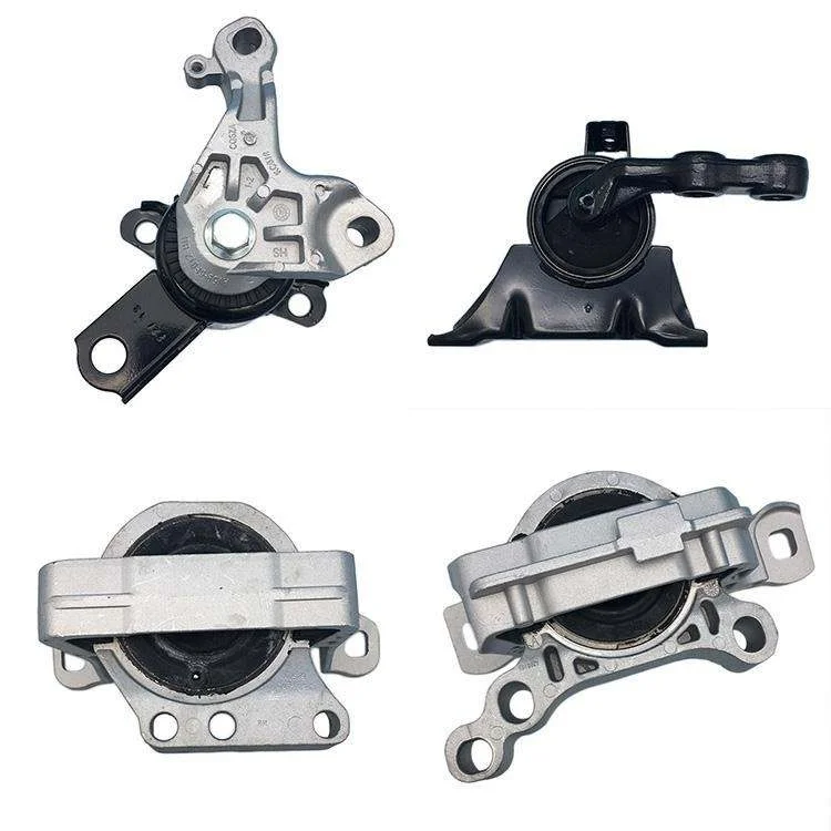
Rubber is a quintessential viscoelastic material: it stores part of the energy elastically (providing support and recovery) while dissipating the remainder as loss (converted to heat). This dual nature makes it function like a “spring” while inherently incorporating “damping.” This is why rubber vibration damping is more effective than “pure springs” at suppressing resonance peaks and mitigating mid-to-high-frequency vibrations and structural noise.Engineering-grade rubber-metal isolators are thus widely used for vibration isolation in general equipment.

First calculate the “frequency ratio,” then evaluate isolation effectiveness
The core indicator of effective vibration isolation is the frequency ratio r = excitation frequency fd / system natural frequency fn.
1) When r≈1, the system enters the resonance zone, where transmission rates significantly amplify. This must be avoided whenever possible.
2) When r < √2 (approximately 1.414), the system often operates in the “amplification zone,” potentially causing the perceived sensation that “vibration damping components actually increase shaking.”
3) Only when r > √2 does the system enter the isolation zone. Engineering practice typically targets higher frequency ratios (e.g., 2.5–4.5; many manuals use ≈3 as an empirical compromise) to achieve more stable and perceptible isolation benefits.
Practical Considerations: In multi-frequency scenarios, prioritize design based on the “lowest operating frequency/lowest rotational speed,” as low frequencies are the most challenging to isolate. Once low frequencies are effectively isolated, higher frequencies are typically easier to isolate.
Reduce natural frequencies using “static deflection”
Static deflection δ refers to the compression/shear deformation of isolators under static load, serving as the bridge mapping “load” to “natural frequency and isolation efficiency.” Greater deflection typically lowers the system’s natural frequency; however, it also imposes stricter requirements on displacement, stability, positioning limits, and service life.
Recommended Selection Steps
1) Convert rotational speed to frequency: Hz = RPM/60.
2) Determine the target frequency ratio r (first avoid resonance, then pursue isolation efficiency).
3) Calculate target natural frequency: fn = fd / r.
4) Consult the supplier’s load-deflection curve based on “single-point actual load” to determine achievable static deflection and corresponding isolation efficiency (avoid simplistic calculations like total weight/number of support points, as center-of-gravity offset may cause overload at certain supports).
5) Always perform dynamic verification for rubber components: Dynamic modulus of rubber typically exceeds static modulus, potentially raising actual natural frequency beyond estimates based solely on static deflection.
Rubber Material Selection
Below aligns common materials with long-tail requirements (oil resistance, weather resistance, temperature resistance, outdoor use, ozone resistance, coolant resistance) to facilitate simultaneous procurement and engineering decisions:
NR Natural Rubber
Typically exhibits excellent rebound and elasticity, suitable for vibration isolation/damping in indoor or non-oily environments; however, it is generally incompatible with oil-based media and requires caution.
CR (Neoprene)
Highly versatile, valued for weather resistance and stability. Often serves as a compromise solution when dealing with oil contamination or outdoor exposure.
NBR (Nitrile)
Typically excels in resistance to petroleum-based media like oil and fuel, making it suitable for rubber vibration isolators/dampers in hydraulic and engine oil environments.
EPDM
Outstanding advantages include weather resistance, ozone resistance, water resistance, and steam resistance, making it suitable for outdoor, humid, and sun-exposed conditions; however, it is generally not recommended for petroleum-based oil environments.
Silicone Rubber
Offers a wide temperature range, suitable for vibration isolation applications with significant temperature fluctuations or stringent thermal requirements (though strength, tear resistance, and cost must be comprehensively evaluated).
Material Selection Recommendations
If you require “rubber vibration isolation performance” while also facing complex media such as oil, ozone, or outdoor exposure, prioritize clearly defining the operating conditions before discussing “which material offers better vibration damping.” Environmental mismatches often lead to aging, expansion, or delamination—issues that can be more critical than theoretical differences in isolation performance.
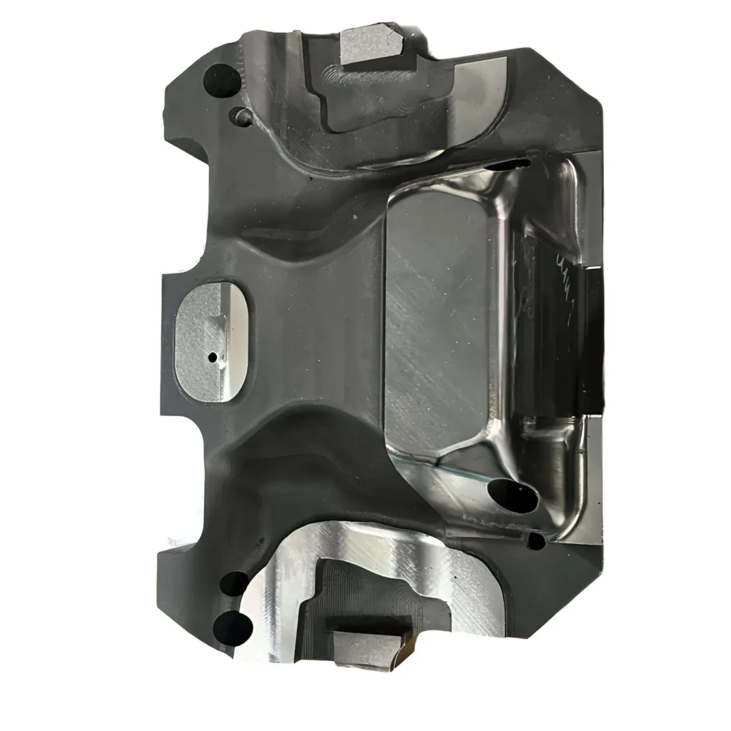
Structure and Design Parameters
1) Load Type: Compression, Shear, or Composite. Shear-type designs typically achieve greater deflection to lower natural frequency; side-mount/wall-mount applications especially require selection based on shear characteristics.
2) Shape Factor: For identical materials and hardness, geometry significantly alters compression stiffness and deflection range—a key reason why “same-hardness rubber exhibits drastically different performance with structural changes.”
3) Rubber-Metal Bonding and Fatigue: Metal inserts, adhesive systems, and vulcanization processes directly impact debonding risk and durability. For long-term operational equipment, incorporate durability/fatigue validation into acceptance testing.
Installation and Field Pitfalls
1) Prevent “short-circuiting”: Piping, cables, rigid mounting brackets, or limiters bypassing isolators render vibration isolation ineffective in the field despite theoretical performance. Post-installation, verify static deflection approaches design values and conduct comparative measurements (acceleration/noise).
2) Foundation Stiffness: Structures on both sides of the isolator must be sufficiently rigid. Otherwise, the foundation/support will deform in series with the isolator, diluting effectiveness. Engineering guidelines commonly require support structure stiffness to significantly exceed isolator stiffness.
3) Don’t focus solely on “load capacity”: Choosing excessive stiffness → results in minimal deflection → insufficient frequency ratio → entry into the amplification zone. This is one of the most common errors.
How to Verify “True Isolation”
To transform vibration isolation from “perception” to “data,” conduct at least two layers of verification:
1) Rapid engineering verification: Compare vibration acceleration/velocity or structural noise at identical locations before and after installation to confirm reduced transmission rates.
2) Systematic dynamic metrics: For dynamic stiffness, transmission stiffness/transmission ratio measurements and terminology frameworks, refer to the ISO 10846 series (along with related research on applying this standard method and error control).
Common Mistakes Checklist
- Ignoring minimum rotational speed/minimum frequency, causing operation or low-speed segments to fall into amplification zones.
- Selecting components based solely on average load, ignoring center of gravity offset leading to corner overload and premature failure.
- Relying solely on static deflection calculations without dynamic verification or actual testing, resulting in overestimated natural frequencies.
- Installation short circuits (piping/cabling/hard stops) causing isolation failure.
Summary
If you’re retrofitting equipment with rubber isolation/vibration damping, the fastest implementation approach isn’t debating “which rubber is best.” Instead, gather all isolation boundary conditions upfront: total weight, center of gravity position/height, number and layout of support points, rotational speed range and minimum operating speed (or minimum excitation frequency), installation orientation (compression/shear/side-mounted), medium environment (oil/coolant/ozone/outdoor), allowable displacement and limiting requirements, target transmission ratio/noise reduction metrics. First define the target frequency ratio, then pre-select using load-deflection curves, and finally validate with dynamic data against field conditions.ozone/outdoor), allowable displacement and limiting requirements, target transmission ratio/noise reduction metrics. Use this data to first determine the target frequency ratio, then pre-select options using load-deflection curves, and finally validate the closed-loop system by comparing dynamic data with field performance.
Submitting this information to Vista Motion typically yields rapid recommendations: rubber vibration damping pad/isolator type suggestions, material proposals (NR/CR/NBR/EPDM/silicone, etc.), target deflection range, installation “short-circuit” risk checklist, and sample/validation suggestions (including dynamic stiffness/durability verification items).This process significantly reduces trial-and-error costs, making vibration isolation performance predictable and verifiable.
FAQ
How to choose between rubber isolators and spring isolators?
For low frequencies (requiring very low natural frequencies), spring isolators are preferred. For mid-to-high frequencies, higher damping requirements, or simplified installation, rubber isolators are more common.
What frequency ratio makes rubber isolators effective?
Frequencies above √2 enter the isolation zone; engineering practice typically selects 2.5–4.5 (or approximately 3) to achieve more stable benefits.
Why does vibration increase after installing rubber vibration damping pads?
This is often due to insufficient deflection causing inadequate frequency ratio, resulting in amplification, or being “short-circuited” by rigid connections from piping/cables.
How is static deflection used for rubber isolator selection?
Determine δ from the load-deflection curve for the actual single-point load, then map it to the target fn and isolation efficiency. Also account for deviations caused by the higher dynamic modulus of rubber.
Which material—NBR, EPDM, CR, or NR—is best suited for “oil-resistant rubber isolators”?
NBR is typically preferred. EPDM is unsuitable for petroleum-based oils. CR often serves as a compromise for general weather resistance and moderate oil resistance scenarios.
Which rubber vibration damping pad provides greater stability for outdoor equipment?
Prioritize EPDM with strong weathering/ozone resistance, and validate formulations and structures based on temperature and UV exposure.
What is the difference between compression-type and shear-type rubber isolators?
Shear-type isolators typically achieve greater deflection and lower natural frequencies; select based on shear characteristics for side-mounted/wall-mounted applications.
Why does the shape factor affect vibration isolation performance?
It determines the “degree of lateral bulge restriction” in rubber under compression, significantly altering compression stiffness and deflection range.
How is the dynamic stiffness/transmission ratio of rubber isolators tested? Are there standards?
Refer to the measurement framework and terminology in the ISO 10846 series (combined with engineering tests using methods like sweep frequency response/FRF).
What information is required for custom rubber isolator design?
Minimum requirements: weight, center of gravity, support point layout, minimum/maximum rotational speed, installation orientation, operating environment, allowable displacement and limits, target transmission ratio/noise specifications. The more complete the information provided, the closer the selection will be to achieving success on the first attempt.