
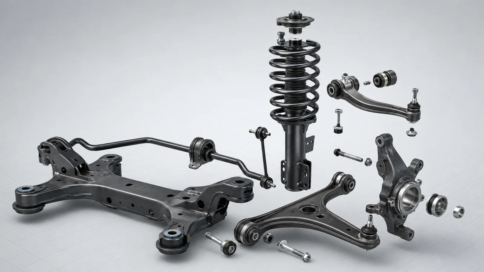
A car suspension is not one part or one standard assembly. It is a system of springs, dampers, wheel-locating members, joints, bushings, roll-control components, and structural mounting parts that manage wheel movement and transfer loads between the road and the vehicle body.
The exact parts list depends on the axle, drivetrain, and suspension architecture. A MacPherson-strut front suspension, for example, does not use the same wheel-locating arrangement as a double-wishbone or multi-link design. A torsion-beam rear axle has a different component set again.
The most useful way to understand the system is therefore not to memorize one universal list, but to group the parts by the job they perform.
| Functional group | Typical parts | Main job |
|---|---|---|
| Elastic elements | Coil springs, leaf springs, torsion bars, air springs | Carry load and allow controlled wheel travel |
| Damping elements | Shock absorbers, dampers, struts | Control the rate of suspension movement and dissipate motion energy |
| Wheel-locating members | Control arms, wishbones, trailing arms, lateral links, radius arms | Guide the wheel through its intended path |
| Articulated joints | Ball joints, spherical joints, link joints | Allow angular movement while transmitting load |
| Roll-control parts | Anti-roll bar, stabilizer links, bar bushings | Distribute roll stiffness between the left and right sides of an axle |
| Isolation and mounting parts | Suspension bushings, top mounts, subframe mounts, spring pads | Transmit load while controlling movement, vibration, and noise |
| Structural and wheel-carrier parts | Steering knuckle, upright, hub carrier, subframe, axle beam | Connect and support the main suspension interfaces |
| Travel-management parts | Jounce bumpers, rebound stops, dust boots | Limit extreme travel or protect moving components |
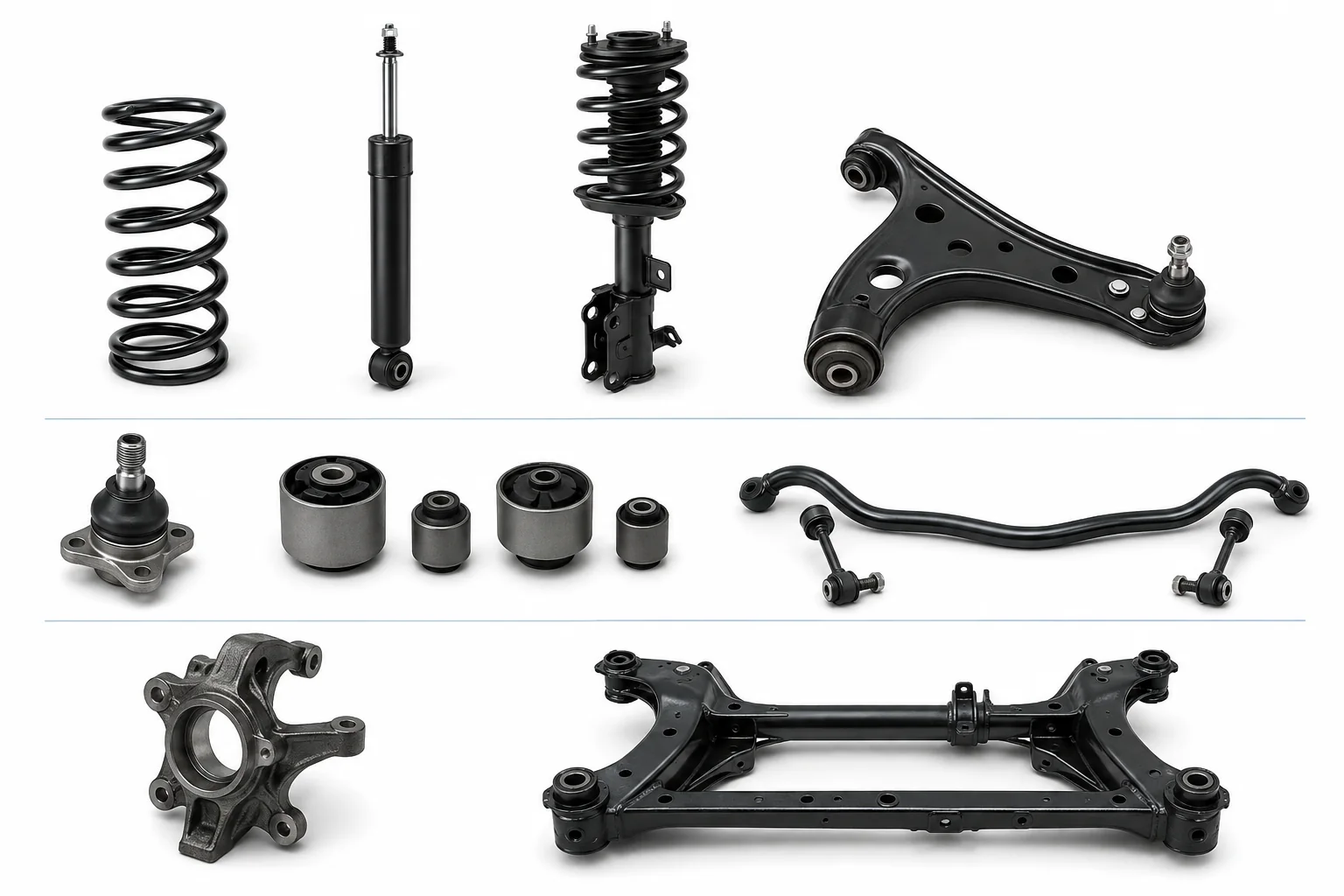
What Counts as Part of a Car Suspension?
In strict engineering terms, a suspension part contributes to one or more of four core tasks: supporting the vehicle, controlling wheel movement, damping motion, or transferring suspension loads into the body or frame.
In everyday repair and parts-catalogue language, the definition is often wider. Steering tie rods, wheel bearings, CV joints, brakes, and tyres may appear in a “suspension parts” diagram because they are physically close to the suspension and can produce similar symptoms. They do not all belong to the suspension system itself.
The strict suspension-system boundary
The suspension sits between the wheel assembly and the vehicle body or frame. Its boundaries include several important interfaces:
- On the wheel side, control arms and links connect through joints to a steering knuckle, upright, or hub carrier.
- On the body side, arms, subframes, axle beams, springs, dampers, and mounts connect to the body or frame.
- At the left-to-right interface, an anti-roll bar may connect the two sides of an axle while still allowing individual wheel movement.
- At compliant interfaces, bushings and mounts allow limited movement while transmitting force and reducing vibration or structure-borne noise.
The steering knuckle or upright is best treated as an interface component: it connects suspension links to the wheel end and, on a steered axle, to the steering system.
| Part | Primary system | Why it is often grouped with suspension parts |
|---|---|---|
| Tie rod and tie-rod end | Steering | Connect the steering gear to the knuckle and move with the suspension |
| Wheel hub and bearing | Wheel end | Mount in or on the knuckle and receive loads passed through the tyre and wheel |
| CV axle and joint | Driveline | Pass through or connect near the wheel carrier on a driven axle |
| Brake caliper and rotor | Braking | Mount at the wheel carrier and add forces at the wheel end |
| Tyre | Tyre/wheel assembly | Provides the first compliant contact with the road but is not normally classified as a suspension component |
This distinction matters in engineering and procurement. If the system boundary is unclear, a drawing package, bill of materials, inspection plan, or supplier quotation can include the wrong interfaces or omit a load path that affects the part being sourced.
Complete Car Suspension Parts List by Function
1. Springs and other elastic elements
The spring element supports the sprung mass and deflects as the wheel moves relative to the body. It stores and releases energy; it does not, by itself, control how quickly the suspension settles after a disturbance.
Common spring types include:
- Coil springs: Helical steel springs used in many passenger-car front and rear suspensions.
- Leaf springs: One or more flexible leaves that can combine springing with axle-location functions, depending on the design.
- Torsion bars: Straight bars that act as springs by twisting.
- Air springs: Flexible air chambers whose pressure and volume contribute to the spring characteristic.
The Society of Automotive Engineers groups coil, leaf, torsion-bar, and pneumatic springs among the principal suspension spring types in its automotive engineering references.1
2. Shock absorbers, dampers, and struts
A damper controls the speed of compression and rebound. It converts suspension-motion energy into heat, helping prevent continued oscillation after a bump or a change in vehicle load.
A conventional shock absorber is mainly a damping device. A strut also performs a structural wheel-location role in the suspension. In a typical MacPherson arrangement, the strut connects the body to the steering knuckle and replaces some of the upper locating members used in other architectures. Monroe’s technical explanation makes the same distinction between an individual shock absorber and a structural strut.2
A strut assembly may also include:
- a coil spring;
- upper and lower spring seats;
- an upper mount and, on a steered axle, a mount bearing;
- a dust boot;
- a jounce bumper;
- attachment hardware.
These items should not automatically be treated as one inseparable product. The service assembly, original vehicle design, and sourcing scope determine whether they are supplied individually or as a module.
3. Control arms and wheel-guiding links
Control arms and links govern the path of the wheel relative to the body. Their geometry influences how wheel alignment parameters change through suspension travel and under load.
Depending on the architecture, the system may use:
- upper and lower control arms;
- A-arms or wishbones;
- trailing or semi-trailing arms;
- lateral links;
- toe links;
- radius arms or tension struts;
- Panhard rods or Watt linkages on some axle layouts.
The name alone does not define the function. In a multi-link system, several smaller links may collectively perform the work that a single wishbone performs in another design.
For a closer look at arm bodies, bushings, ball joints, and architecture-specific layouts, see What Are Vehicle Control Arms?.
4. Ball joints and articulated connections
Ball joints and similar articulated joints allow angular movement while carrying forces between links and the wheel carrier. A steered suspension needs joints that can accommodate both suspension travel and steering rotation.
The joint may be:
- integrated into a control-arm assembly;
- pressed into the arm or wheel carrier;
- flange-mounted or bolted;
- supplied as a separate service component.
The interface specification should identify the joint location, articulation range, load directions, attachment method, sealing requirements, and any critical tapers or fits.
5. Anti-roll bars, links, and bushings
An anti-roll bar, also called a sway bar or stabilizer bar, couples the left and right sides of an axle through torsional stiffness. It primarily resists the difference in suspension movement between the two sides, such as during cornering, while allowing more equal movement during some straight-line road inputs.
The assembly commonly includes:
- the formed torsion bar;
- chassis or subframe mounting bushings and brackets;
- end links or stabilizer links;
- ball-joint or bushing interfaces at the links.
Not every axle uses an anti-roll bar, and the bar diameter, lever-arm geometry, bushing design, and installation position are application-specific.
6. Suspension bushings and mounts
Bushings create compliant pivots between components. Common locations include control arms, trailing arms, anti-roll bars, subframes, axle beams, dampers, and strut top mounts.
Many of these parts use rubber bonded to metal. ZF describes rubber-to-metal chassis components as connections that transfer compression and shear forces while isolating oscillation, vibration, and structure-borne noise.3 The design may use solid rubber, voided geometry, multiple rubber sections, or a fluid-filled arrangement, depending on the required directional stiffness and damping behaviour.
Other mounting and isolation components include:
- spring pads and isolators;
- strut top mounts;
- damper eye bushings;
- subframe mounts;
- axle-beam bushings;
- rebound and jounce buffers.
For a more detailed discussion of bushing locations and functions, see What Are Suspension Bushings and Their Role in Vehicle Performance?.
7. Steering knuckles, uprights, and hub carriers
These wheel-carrier components form the central interface between the suspension links and the rotating wheel assembly. Depending on the axle, they may provide mounting points for control arms, ball joints, struts, tie rods, wheel bearings, drive shafts, and brakes.
Terminology varies by design and market. “Steering knuckle” is common for a steered wheel; “upright” and “hub carrier” are also used, including for non-steered rear wheels.
8. Subframes, crossmembers, axle beams, and solid axles
These larger structural parts establish the mounting base for other suspension components and transfer their loads into the vehicle structure.
- A subframe or crossmember can carry control arms, anti-roll bars, steering gear, suspension mounts, or powertrain mounts.
- A torsion beam combines left and right trailing-arm functions with a cross-member that provides a designed amount of torsional compliance.
- A solid axle connects the wheel carriers on the same axle through a rigid member.
- An axle housing may also carry driveline components when the axle is driven.
9. Jounce bumpers, rebound stops, and protective parts
Travel-management parts act near the limits of suspension movement or protect sliding and sealing surfaces.
- A jounce bumper progressively or abruptly limits compression travel, depending on its design.
- A rebound stop limits extension travel in applications that require it.
- A dust boot shields a damper rod or seal area from contamination.
Although small, these components interact with the available travel, local loads, packaging, noise, and durability of the surrounding assembly.
How Do Suspension Parts Work Together?
When a tyre passes over a road input, force moves through the wheel and wheel carrier into the suspension links, spring, damper, bushings, and mounting structure. Each group handles a different part of the event:
- The wheel carrier and links guide the wheel along the designed path.
- The spring deflects and stores energy while supporting the vehicle load.
- The damper controls the speed of compression and rebound.
- Bushings and mounts permit designed compliance and filter selected vibration paths.
- The subframe, axle structure, or body mounting points distribute the remaining loads into the vehicle structure.
During braking and acceleration, the same components also transmit longitudinal forces. During cornering, they transmit lateral forces and moments while the spring, anti-roll bar, dampers, links, and bushings influence body roll and wheel-position control.
This is why a suspension component cannot be specified only by its external shape. Its load directions, installed orientation, movement range, interfaces, compliance, and relationship with adjacent parts all affect its function.
What Is the Difference Between Front and Rear Suspension Parts?
Front and rear suspensions share the same fundamental tasks, but their interfaces often differ.
Front suspension components
A front suspension on a passenger car commonly includes a steering interface. The steering knuckle turns, and the ball joints, strut mount bearing, or other pivots must allow steering rotation while the wheel moves vertically.
On a driven front axle, the layout must also accommodate a drive shaft and CV joints. Packaging around the engine, transmission, steering gear, brakes, and wheel can constrain the position of the control arms, strut, and subframe.
For a deeper front-axle breakdown, see What Are the Parts of the Front Suspension?.
Rear suspension components
A rear suspension may use trailing arms, semi-trailing arms, multiple links, a torsion beam, a solid axle, leaf springs, or another arrangement. A rear steering interface is absent on many vehicles, but some vehicles use passive or active rear-steer functions.
The rear layout may also need to package a differential, half-shafts, fuel or battery systems, exhaust components, and cargo-floor structure. As a result, “rear suspension parts” is not one fixed list.
How Does Suspension Architecture Change the Parts List?
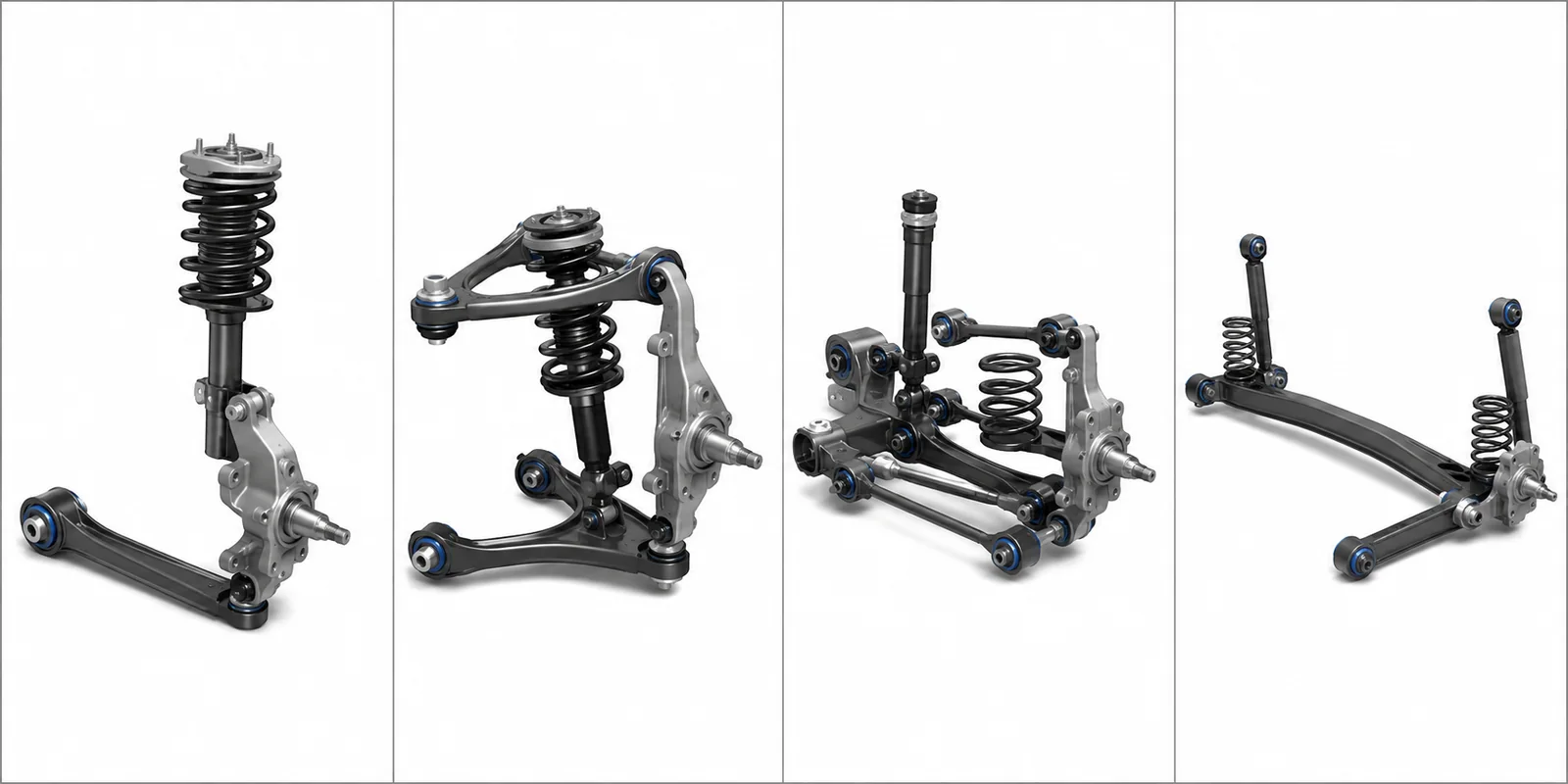
| Architecture | Typical locating arrangement | Parts-list implications | Important qualification |
|---|---|---|---|
| MacPherson strut | Structural strut plus lower control arm and joints | Usually no conventional upper control arm; top mount and bearing become important interfaces | Exact geometry and auxiliary links vary |
| Double wishbone | Upper and lower arms locate the upright | More arm and joint interfaces; spring and damper may be separate or combined | Arm shape and spring location vary widely |
| Multi-link | Several links independently or collectively locate the wheel | More individual links, joints, and bushings; names differ by manufacturer | “Five-link” or another count does not by itself define every function |
| Torsion-beam rear | Trailing arms connected by a torsionally compliant beam | Beam assembly can combine wheel location and roll-stiffness functions | Bushings, spring, and damper mounting differ by vehicle |
| Solid axle or live axle | Rigid axle connects both wheel ends | May use leaf springs or separate links, plus lateral location and dampers | Driven and non-driven arrangements differ |
| Air or adaptive suspension | Air spring or controlled damper added to a locating architecture | May add an air supply, sensors, valves, electronic control, or adjustable dampers | Air/adaptive technology does not replace the need for wheel-location geometry |
SAE engineering references treat MacPherson, double-wishbone, multi-link, trailing-arm, and solid-axle arrangements as distinct suspension categories or design templates.4 A correct component list should therefore identify the architecture before defining the bill of materials.
Which Suspension Parts Use Rubber-to-Metal Components?
Rubber-to-metal components are used where a connection must transmit load but cannot behave like a completely rigid joint. Typical examples include:
- control-arm and wishbone bushings;
- trailing-arm and axle-beam bushings;
- anti-roll-bar mounting bushings;
- subframe mounts;
- strut top mounts and damper eye bushings;
- selected spring seats, isolators, and travel buffers.
Their job is not simply to “make the ride softer.” The component may need to be stiff in one direction, more compliant in another, control a rotation axis, maintain geometry under braking, and reduce a selected vibration path at the same time.
Hardness, stiffness, geometry, and damping are not the same
Rubber hardness is a material measurement. The installed stiffness of a bushing is a system response influenced by the compound, rubber volume, geometry, voids, metal inserts, bonding area, preload, loading direction, amplitude, frequency, temperature, and installation condition.
Two bushings made with rubber of similar hardness can therefore have different force-displacement behaviour. For design or sourcing, a hardness value alone is rarely a complete functional specification.
Useful engineering inputs may include:
- radial, axial, torsional, or conical load directions;
- target force-displacement or stiffness characteristics;
- permitted displacement and articulation;
- static, peak, and repeated load conditions;
- frequency- and temperature-dependent requirements;
- exposure to water, road salt, oils, fuels, heat, or other media;
- required bonding, fatigue, dimensional, and environmental validation.
Engineering and Procurement Checklist for Custom Suspension Parts
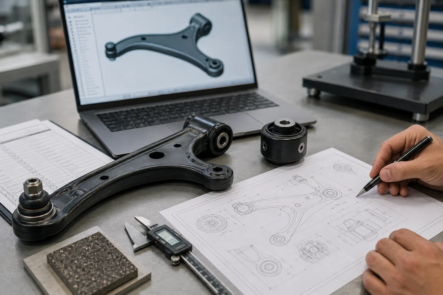
A useful RFQ does more than identify a part name. It describes the installed system, critical interfaces, performance target, and evidence needed for approval.
Vehicle and operating conditions
- Vehicle or equipment type and axle location
- Suspension architecture and component function
- Sprung and unsprung interfaces
- Static, peak, impact, braking, cornering, and torsional load information, where available
- Motion envelope, articulation, and suspension travel
- Operating temperature and environmental exposure
- Road, duty-cycle, durability, and NVH requirements
Drawings, models, and interfaces
- 2D drawings and 3D models
- Datum system and critical dimensions
- Fits, hole patterns, tapers, threads, and bearing or joint interfaces
- Geometric tolerances and critical-to-function characteristics
- Installed orientation, clocking, preload, and assembly condition
- Mating-part information where it affects manufacturability or function
Material and manufacturing requirements
- Required material specifications or approved alternatives
- Heat treatment and surface-treatment requirements
- Rubber compound or performance requirements
- Rubber-to-metal bonding requirements
- Weld, casting, forging, machining, moulding, or assembly notes, as applicable
- Restricted substances and market-specific documentation requirements
Validation and quality requirements
- Dimensional inspection plan
- Material verification
- Static and fatigue test requirements
- Stiffness or force-displacement validation
- Bond-strength or adhesion validation for bonded parts
- Corrosion or environmental testing
- Sample approval and production part approval requirements
- Traceability, records, and change-control expectations
Commercial and programme inputs
- Project stage and target application
- Prototype or sample quantity
- Estimated annual demand
- Target milestones
- Packaging and delivery destination
- Required quotation breakdown and documentation
Not every project needs every item at the first contact. However, missing functional and interface information should be identified before a supplier commits to a manufacturing route or performance claim.
Common Suspension-Part Specification and Sourcing Mistakes
Treating one parts list as universal
The same part name can describe different functions, and different architectures can use different components to achieve a similar wheel path. Identify the axle and architecture first.
Mixing suspension, steering, wheel-end, and driveline scope
Closely connected systems share loads and packaging. Define the quotation boundary and mating interfaces instead of relying on a generic “suspension kit” description.
Selecting a part by appearance or nominal dimensions
Two parts can look interchangeable but differ in material, heat treatment, joint articulation, bushing orientation, stiffness, tolerances, or validation requirements.
Specifying an elastomeric part by hardness alone
Hardness does not fully define the installed force-displacement response, directional compliance, damping, or durability of a bushing.
Sending a drawing without the operating conditions
A drawing can define geometry while leaving the load case, motion, environment, life target, and acceptance method unclear. Those conditions are needed to evaluate design and process risk.
Comparing suppliers on unit price before evidence
For a safety- and geometry-related component, the quotation should be read together with the proposed material, process route, validation plan, inspection method, change control, and traceability requirements.
What Should You Send for an Engineering Review or Quote?
For an initial review, send as much of the following as is available:
- part name, axle position, and suspension architecture;
- 2D drawing, 3D model, or representative sample information;
- material and surface-treatment requirements;
- critical dimensions and tolerances;
- load, movement, stiffness, damping, NVH, and environmental requirements;
- required tests and approval documents;
- prototype quantity, estimated annual demand, and destination market.
Vista Motion accepts enquiries for custom components across the suspension system rather than limiting projects to a fixed catalogue. Each enquiry is reviewed against the component geometry, material, operating conditions, manufacturing route, validation requirements, and commercial scope before a quotation is prepared.
Submit your drawings or application requirements for a project-specific manufacturability and quotation review.
Frequently Asked Questions
Are tie rods part of the suspension?
Tie rods belong primarily to the steering system. They connect the steering gear to the steering knuckle and work through the same moving wheel-end interface, which is why they are often included in broad steering-and-suspension catalogues.
Are wheel bearings suspension parts?
Wheel bearings belong to the wheel-end assembly. They mount in or on the knuckle or hub carrier and receive loads transmitted through the wheel, so they are closely connected to the suspension without being a wheel-locating spring or damper component.
Is a strut the same as a shock absorber?
No. Both provide damping, but a strut also acts as a structural part of the wheel-locating assembly. A conventional shock absorber mainly controls motion and is not normally the principal member locating the wheel.2
Does every car have the same suspension parts?
No. The component set depends on the front or rear axle, driven or non-driven layout, vehicle packaging, and architecture such as MacPherson, double wishbone, multi-link, torsion beam, or solid axle.
Which suspension parts commonly contain rubber bushings?
Common examples include control arms, trailing arms, anti-roll-bar mounts and links, subframes, axle beams, damper eyes, and strut top mounts. The exact number, geometry, and material design are application-specific.
References
-
SAE International, Automotive Engineering, suspension system components and suspension types, accessed August 28, 2026: https://www.sae.org/images/books/toc_pdfs/R199.pdf↩
-
Monroe, “Shocks vs. Struts: What’s the Difference?”, accessed August 28, 2026: https://www.monroe.com/technical-resources/shocks-101/shocks-vs-struts.html↩↩
-
ZF Aftermarket / LEMFÖRDER, “Steering and Chassis Parts—Rubber-to-Metal Components,” accessed August 28, 2026: https://aftermarket.zf.com/en/aftermarket-portal/our-portfolio/passenger-cars/products/steering-chassis-parts/↩
-
SAE International, “A Tool for Rapid Vehicle Suspension Design,” Technical Paper 2004-01-3543: https://saemobilus.sae.org/papers/a-tool-rapid-vehicle-suspension-design-2004-01-3543↩
