
This article will provide a detailed overview of the working principles, key advantages, and practical limitations of finite element analysis from the perspective of engineering applications, as well as how it helps improve the design of rubber vibration dampers, engine mounts, and other mechanical components.
What Is Finite Element Analysis?
Finite element analysis is an engineering analysis method that uses computer-based numerical calculations to study the behavior of structures or physical systems.
You can think of it this way: before manufacturing a real product, a digital model is created and subjected to loads that closely mimic actual operating conditions to observe how it might deform, be subjected to forces, vibrate, or transfer heat.
Finite Element Analysis is primarily based on the Finite Element Method (FEM).
There is a distinction between the two:
- Finite Element Method (FEM): A mathematical numerical method that approximates solutions to physical problems by discretizing a complex continuum into a finite number of elements.
- Finite Element Analysis (FEA): The application of the Finite Element Method to the modeling, solving, result interpretation, and design evaluation of real-world engineering problems.
Here’s a simple example.
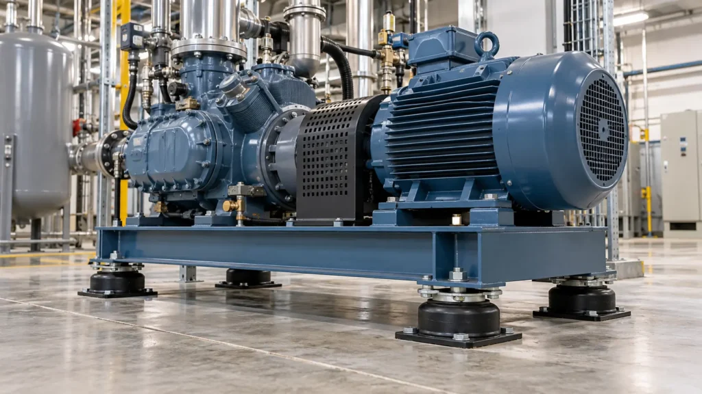
Suppose you are developing a rubber vibration-isolation mount for an industrial compressor. The equipment’s weight, installation location, and operating frequency have already been determined, but you do not yet know whether the current rubber structure can provide adequate support stiffness.
The traditional approach might involve first manufacturing a prototype, installing it on the equipment, and then conducting tests to determine whether the design needs to be adjusted.
With FEA, you can first create a 3D model of the mount, input the rubber material parameters, metal component properties, loads, and mounting constraints, and observe the changes in displacement, strain, stress, and reaction forces under different designs.
If a preliminary analysis reveals excessive deformation in a certain area, you can adjust the rubber thickness, structural shape, or metal support layout before manufacturing the mold.
Of course, the final design still needs to be validated through necessary experiments and under actual operating conditions.
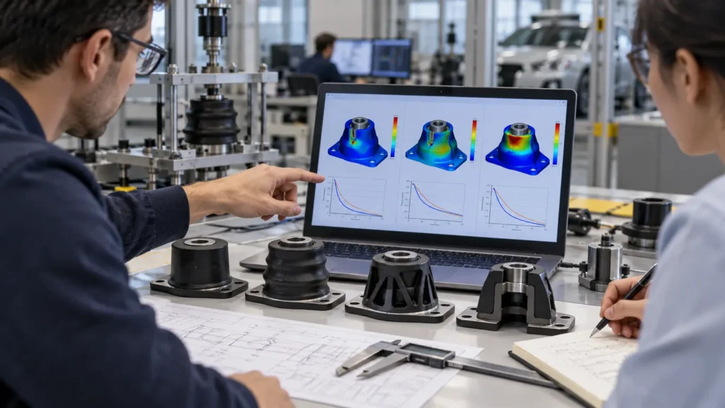
What steps are typically involved in finite element analysis?
Step 1: Model creation. Create or import the product geometry based on CAD drawings, and identify the components to be analyzed along with their connection relationships.
Step 2: Define materials and operating conditions. Input the material’s mechanical properties, loads, constraints, contact relationships, and necessary environmental parameters.
Step 3: Meshing and Solving. Discretize the model into multiple finite elements and calculate displacements, strains, stresses, or other physical responses.
Step 4: Evaluate results. Inspect critical areas, determine whether design requirements are met, and, as needed, make model corrections, perform mesh convergence checks, and conduct experimental validation.
Among these steps, result evaluation is particularly important. While the software can generate calculation results, determining whether these results are reasonable still requires engineering knowledge and an understanding of real-world operating conditions.
Eight Core Advantages of Finite Element Analysis
The reason finite element analysis is widely used in mechanical design, automotive engineering, aerospace, industrial equipment, and structural engineering is not merely because it can generate intuitive stress contour plots.
More importantly, it provides a systematic analytical basis for engineering decision-making.
Advantage 1: Identifying Potential Structural Issues Before Manufacturing
Many design flaws in mechanical components are not apparent in static drawings.
For example:
- A stress concentration may exist at a certain joint.
- An overly thin structure may undergo excessive deformation under maximum load.
- A mounting area may fail to distribute loads evenly.
- Local contact pressure may exceed expectations.
These issues may not become apparent immediately during product assembly but may gradually emerge as the product is used over time.
FEA can help engineers observe the mechanical response inside the structure—which is difficult to measure directly—and identify critical areas that require further inspection.
This is particularly important for rubber-metal composite vibration dampers.
Rubber typically has a high degree of deformability, while metal components have relatively high stiffness. The two materials behave differently under load, and the local deformation and stress conditions at the interface may be more complex than in a single-material structure.
Through proper finite element modeling, engineers can evaluate the strain distribution in the rubber body, the forces acting on the metal components, and potential risk areas near the interface.
Practical Value: Helps you identify design details requiring modification early in product development, rather than having to redesign after prototype testing fails.
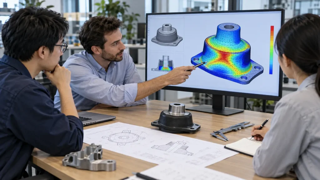
Advantage 2: Optimize structural design to balance strength, stiffness, and weight
In mechanical design, thicker, heavier, and sturdier does not necessarily mean better.
A structural component may have sufficient strength, but an overly conservative design can increase material usage, manufacturing costs, and overall weight.
Conversely, excessive weight reduction may lead to insufficient stiffness, local buckling, or fatigue risks.
One of the advantages of finite element analysis is that it helps engineers find a reasonable balance among these performance objectives.
For example, when designing a rubber vibration-damping mount, you may need to consider the following simultaneously:
- whether the mount can support the equipment’s static weight;
- Whether the rubber compression is within a reasonable range.
- Whether the metal bracket has sufficient strength.
- Whether the overall stiffness meets vibration isolation requirements.
- Whether the design facilitates manufacturing and installation.
Engineers can develop multiple design options and analyze the effects of different rubber thicknesses, structural profiles, and metal component dimensions.
All other conditions being equal, FEA can help compare the load-displacement behavior and local stress distributions of these alternatives.
However, it should be emphasized that the design with the highest strength does not necessarily provide the best vibration isolation.
For rubber vibration isolators, the design often needs to balance load-bearing capacity, positioning, dynamic stiffness, damping, deformation space, and service life.
Finite element analysis provides a basis for design decisions rather than simply making all structures sturdier.
Advantage 3: Reduced Costs for Unnecessary Physical Prototypes and Pilot Production
Developing a new product typically involves design, prototyping, testing, adjustment, and re-validation.
When product structures are complex, tooling costs are high, or testing conditions are stringent, multiple prototyping iterations can increase project costs.
Finite element analysis allows for preliminary screening of multiple candidate designs before manufacturing prototypes.
For example, suppose you need to develop a custom rubber bushing and are comparing three different rubber cross-sectional structures.
If you were to manufacture three sets of molds directly for testing, you would likely have to bear the costs of mold machining, materials, production, and testing separately.
However, through proper FEA simulation (finite element analysis), engineers can first compare the deformation and stiffness performance of these designs under specified loads, and then select the most promising design to proceed to the prototyping stage.
This approach has the potential to reduce low-value design iterations.
However, simulation cannot completely replace physical testing.
Especially for rubber vibration dampers, actual performance is also influenced by material formulation, vulcanization process, temperature, loading frequency, and manufacturing consistency.
Therefore, a more reasonable approach is not to eliminate testing altogether, but to focus testing on the design options most worthy of validation.
The key to true cost savings lies in reducing trial-and-error iterations that lack a solid analytical basis.
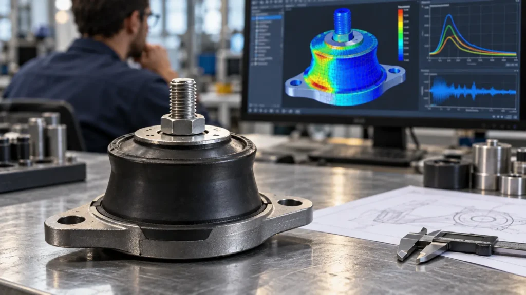
Advantage 4: Shorter Product Development Cycles
In mechanical manufacturing projects, design modifications themselves are not necessarily complex; what is truly time-consuming is often the re-machining, scheduling of tests, and waiting for results.
Finite element analysis allows engineers to compare the effects of design modifications in a digital model.
For example, an engine mount exhibited excessive stiffness during the prototype stage.
If a properly validated finite element model had already been established, engineers could analyze the potential effects of changing the rubber’s geometry, local thickness, or structural cavities without having to immediately produce a physical prototype for every modification.
Of course, every major design change requires re-evaluating the model’s applicability; one cannot assume that the original model is accurate under all conditions.
This combined approach of design and analysis is particularly well-suited for custom parts that require iterative adjustments to structural parameters.
It also helps R&D, procurement, and manufacturing teams understand the reasons for design changes earlier, reducing rework caused by insufficient technical communication.
Advantage 5: Analysis of Complex Geometries and Multiple Load Conditions
Many engineering components are not subjected to loads in a single direction.
In actual operation, a component may be subjected to pressure, shear force, torque, impact, and cyclic vibration simultaneously.
For structures with complex shapes, multiple connections, or combinations of multiple materials, it is often difficult to fully reflect their local mechanical response by relying solely on simple manual calculations.
Finite element analysis enables the creation of more detailed numerical models tailored to specific problems.
Take rubber bushings as an example; engineers may need to study:
| Loads or operating conditions | Key Analysis Areas |
| Radial loads | Radial deformation, reaction forces, and local strain |
| Axial loads | Axial stiffness, rubber compression and tensile response |
| Torsional Loads | Torsional stiffness, shear deformation, and strain distribution |
| Combined Loads | Structural response under combined loads in different directions |
| Cyclic Loads | Dynamic stiffness, frequency response, and potential fatigue risks |
By establishing appropriate load combinations, engineers can evaluate designs under conditions that more closely resemble the product’s actual operating conditions.
However, a more complex model does not necessarily mean more reliable results.
If the actual installation method, material parameters, or boundary conditions are set incorrectly, the results may still deviate from reality, even if the mesh is very fine.
Therefore, the validity of the model is always more important than how complex it appears to be.
Advantage 6: Improved Vibration Performance
For the rubber vibration damping products that Vista Motion focuses on, this advantage of finite element analysis has direct engineering value.
Rubber vibration isolators do not simply absorb all vibrations through soft materials.
Their actual performance depends on factors such as system stiffness, damping, mass, excitation frequency, load direction, and installation conditions.
Suppose a piece of industrial equipment generates significant vibration at a specific rotational speed, and you want to use rubber mounts to reduce the transmission of vibration to the mounting foundation.
If the mount is too stiff, it may be difficult to achieve the expected vibration isolation effect; if it is too soft, it may cause excessive static displacement, affecting the equipment’s positioning and stability.
In this case, finite element analysis can be applied to the design at two levels.
The first level is component design.
Analyzing the deformation and stiffness of rubber mounts under compression, shear, or combined loads helps engineers adjust their geometric structure and material selection.
The second level is the evaluation of the system’s dynamic performance.
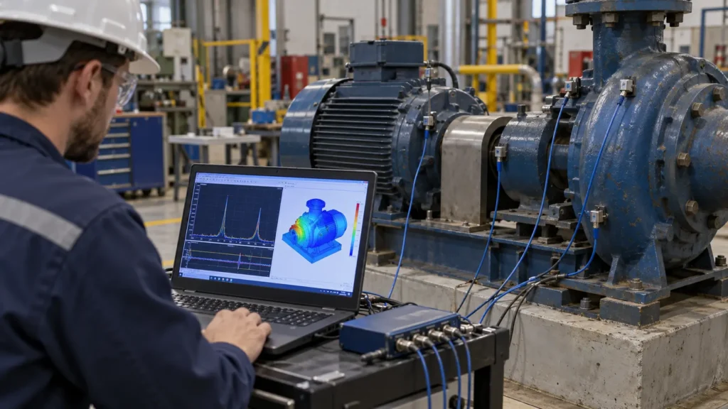
Combined with an appropriate system model, modal analysis or frequency response analysis is performed to study the system’s natural frequencies, mode shapes, and response within the operating frequency range.
It should be noted that static finite element analysis of components cannot directly prove the vibration isolation performance of the entire equipment.
To predict actual vibration transmission, it is also necessary to consider the equipment’s mass distribution, installation stiffness, excitation conditions, and frequency-dependent material properties.
For purchasers, this means that when selecting vibration isolators, they cannot simply look at product dimensions and rubber hardness.
They should also determine whether the isolator is compatible with the equipment’s actual operating conditions.
Advantage 7: Aids in Assessing Durability and the Risk of Fatigue Failure
Many mechanical components fail not because of a single excessive load, but because of gradual damage caused by long-term repetitive stress.
Engine mounts, rubber bushings, and industrial vibration isolators are typical examples.
These products may be subjected to cyclic compression, shear, or complex dynamic loads over long periods.
Finite element analysis helps engineers identify areas of high strain, high stress, or localized energy concentration, and provides input for subsequent fatigue analysis.
For example, when developing rubber-to-metal bushings, engineers can use simulation to identify areas in the rubber structure that may be subjected to high strain, and then evaluate whether the cross-sectional shape or local connection structure needs to be adjusted.
However, stress contour plots cannot be directly equated with product life predictions.
Estimating fatigue life often requires appropriate fatigue damage models, experimental material data, real load spectra, and corresponding validation results.
Rubber materials may also exhibit significant time dependence, temperature sensitivity, and cyclic loading effects.
If these factors have a significant impact on the usage scenario, the long-term reliability of the product cannot be determined based solely on a single static linear analysis.
A reasonable engineering approach is to use finite element analysis to identify risk areas and then combine this with material testing and durability testing to improve the reliability of design decisions.
Advantage 8: Improving Design Communication Efficiency
For suppliers of custom mechanical components, technical communication often determines whether a project can proceed smoothly.
The buyer may ask:
“Why does this area need to be thickened?”
“How will the vibration-damping performance change if the rubber’s shape is modified?”
“Can the existing structure withstand greater lateral loads?”
If only two-dimensional drawings are available, engineers often have to spend a significant amount of time explaining these issues.
However, well-annotated deformation diagrams, load-displacement curves, strain distribution maps, or comparative analysis results can provide all parties with a more intuitive understanding of the rationale behind design changes.
When discussing different design options, the engineering team can also clearly distinguish which conclusions are based on simulation predictions and which have been verified through physical testing.
This transparency not only benefits technical staff but also helps procurement teams understand manufacturing costs, development cycles, and design risks.
For long-term OEM partners, traceable engineering analysis and validation records are particularly valuable.
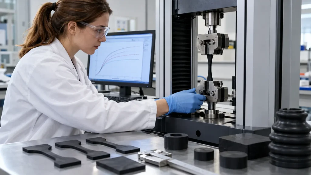
Why is finite element analysis particularly important for the design of rubber vibration dampers?
Finite element analysis is applicable to a wide range of mechanical structures, but rubber vibration dampers present some unique challenges.
Their performance is not only related to their shape but also depends on the complex mechanical properties of rubber materials and the method of connection between rubber and metal.
Rubber is a typical nonlinear material
Within the range of small deformations, preliminary calculations for certain metal structures can be performed using linear elastic models.
However, rubber typically undergoes significant elastic deformation, and its stress–strain relationship often cannot be described simply by a linear model.
In finite element analysis, engineers may need to select an appropriate hyperelastic material model, such as the Mooney-Rivlin or Ogden model.
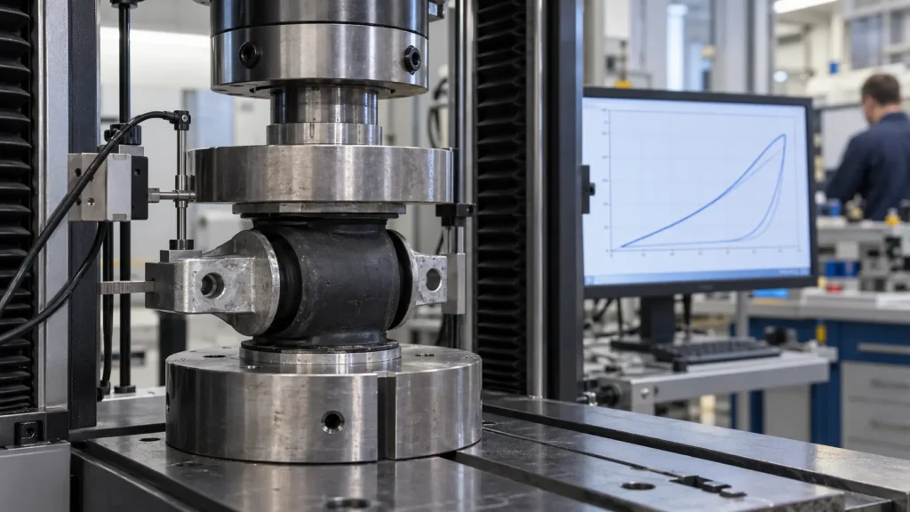
These models can be used to describe the large-deformation behavior of rubber under specific conditions, but the model parameters typically need to be fitted based on relevant material test data.
The appropriate model and parameters may vary depending on the rubber formulation, deformation range, and loading method.
Therefore, simply using generic rubber parameters from the software’s material library does not guarantee accurate simulation results.
For rubber vibration damping products with high performance requirements, material testing and model calibration should be an integral part of the design process.
Rubber stiffness directly affects the performance of vibration damping systems
When selecting rubber vibration isolators, people often focus on Shore A hardness.
Hardness is indeed an important material indicator, but it does not fully represent the actual stiffness of the vibration isolator.
Even if two products use rubber of similar hardness, their stiffness may differ significantly depending on their geometry, load-bearing area, degree of rubber constraint, and installation method.
Engineers need to distinguish between static stiffness and dynamic stiffness.
Static stiffness primarily describes the load-displacement response of a component under quasi-static loading.
Dynamic stiffness, on the other hand, is related to vibration loading conditions and is typically influenced by frequency, temperature, deformation amplitude, and the viscoelastic properties of the material.
For engine mounts, industrial equipment mounts, and other vibration-isolation components, dynamic performance often determines how the product performs in actual operation.
Therefore, a sound design must not only meet load-bearing requirements but also evaluate the operating frequency range and dynamic response.
Special Attention Must Be Paid to the Rubber-to-Metal Interface
Many vibration-isolation components employ rubber-metal composite structures.
For example, engine mounts, torsional bushings, and some industrial vibration isolation mounts typically rely on rubber deformation to achieve a certain degree of flexible connection, while the metal structure handles installation and load transfer.
Due to significant differences in material stiffness, complex strain distributions may occur in the interface.
Finite element analysis can help identify high-risk areas in the rubber body and near the connection, supporting geometric optimization.
However, if it is necessary to predict delamination or peeling at the rubber-to-metal interface, appropriate interface failure models and experimental parameters must also be considered. A standard fully bonded model cannot guarantee that the actual bond strength is sufficient.
This is why quality control for rubber-to-metal products cannot be limited to the design phase alone.
Metal surface treatment, bonding processes, vulcanization conditions, and necessary bonding performance tests can all affect the consistency and reliability of the final product.
Products May Perform Differently Under Different Temperatures and Loads
A rubber shock absorber that performs well at room temperature may not exhibit the same performance in all operating environments.
For example, certain rubber formulations may harden at low temperatures and exhibit varying degrees of performance changes in high-temperature environments.
Long-term compression may also involve issues such as stress relaxation, creep, or permanent compression set.
If the product is used in construction machinery, marine power equipment, or other systems with complex operating conditions, it is necessary to evaluate during the design phase whether these factors will affect product performance.
Provided that material data is sufficient and the analysis model is appropriate, FEA can help compare structural responses under specific temperature and load conditions.
For issues involving aging and long-term performance changes, additional material models and specialized experiments may be required.
What is the difference between finite element analysis and traditional physical testing?
When many engineers first encounter FEA, they often ask: Since product performance can be predicted using a computer, is it still necessary to invest time and money in real-world testing?
The answer is yes, but the two serve different purposes.
| Comparison of Projects | Finite Element Analysis (FEA) | Physical Prototype Testing |
| Primary Purpose | To predict product response under specific assumptions and assist in comparing design options | To observe the performance of actual prototypes under specified test conditions |
| Design Modifications | Typically facilitates the comparison of multiple design parameters | Some modifications require the remanufacture of prototypes |
| Internal stresses and strains | Predict field distributions within the model | Are typically limited by the measurement location and sensing method |
| Actual material behavior | Depends on the material model and its parameters | Can reflect the actual response of the tested specimen |
| Impact of Manufacturing Defects | require specialized modeling to be captured | May be revealed during relevant inspections and tests |
| Key Limitations | Affected by input data, model assumptions, and numerical errors | Subject to limitations regarding the number of test specimens, test conditions, and cost |
For simple structures, manual calculations or basic testing may be sufficient.
For complex nonlinear structures, structures subjected to forces in multiple directions, or custom products requiring multiple revisions, the value of finite element analysis is often more evident.
A sound engineering process typically does not involve choosing between FEA and physical testing, but rather combines the two based on project risks and technical requirements.
What are the limitations of finite element analysis? Why are the results not always accurate?
When discussing the advantages of finite element analysis, it is also essential to clearly understand its limitations.
Any simulation is based on a set of model assumptions.
If actual operating conditions differ from these assumptions, the analysis results may show significant deviations.
Inaccurate Material Parameters
Rubber formulations, material batches, temperature, and loading history can all affect actual mechanical properties.
If the input material data does not accurately represent the actual material, the calculation results may lose reliability.
For nonlinear rubber materials, it is recommended to use appropriate experimental data to determine the material model parameters according to project requirements.
Loads and Boundary Conditions Do Not Reflect Actual Conditions
If the model completely fixes connections that are actually flexible, the calculated stiffness, displacement, or stress may differ from the actual assembly state.
Similarly, if important lateral loads or impact conditions are ignored, certain design risks may be underestimated.
Therefore, understanding how the product is installed and used is just as important as creating a detailed model.
Unreasonable Mesh
Finite element analysis requires dividing the geometric structure into computational elements.
An overly coarse mesh may fail to adequately describe the response in critical areas, while inappropriate local refinement does not necessarily improve the reliability of the results.
Engineers should perform appropriate mesh convergence checks based on the response variables of interest.
Special treatment may also be required for contact areas, local geometric changes, and high-strain regions.
Simulation Results Lacking Experimental Validation
A vivid color-coded stress map does not mean that the design has been validated.
For critical load-bearing components or vibration-damping products with high performance requirements, actual testing must be conducted to determine whether the calculation results are reliable.
If necessary, a sensitivity analysis of material parameters should also be conducted to understand the extent to which changes in input parameters affect the results.
The value of FEA lies in correct engineering modeling, reasonable interpretation of results, and appropriate validation—not in images automatically generated by the software.
In which situations is it most worthwhile to use finite element analysis?
Not all components require complex finite element calculations.
If the structure is simple, the operating conditions are well-defined, and a mature, fully validated design already exists, standard calculation methods and conventional testing may be more cost-effective.
However, FEA is generally worth considering in the following situations:
New product development. When there is insufficient historical usage data for a component, finite element analysis can help evaluate the initial design.
Complex structures or multi-material assemblies. When a product features complex geometries, contact interactions, or rubber-metal composite structures, FEA helps understand its local response.
Multi-directional loading. When a part is subjected to a combination of axial, radial, or torsional loads, appropriate analysis methods can be used to compare different operating conditions.
High performance requirements. When customers have specific requirements for displacement, stiffness, strength, or vibration characteristics, simulation can support design screening.
High prototyping costs. If the mold is complex or the cost per prototype run is high, conducting a reasonable analysis in advance may offer economic value.
Performance improvements for existing products. For components exhibiting abnormal deformation, vibration, or localized damage, finite element analysis can assist in investigating potential causes.
You don’t have to use a technology simply because it is advanced.
A more important question to consider is: Can it help solve engineering problems in the current project that cannot be adequately addressed through simple methods?
Applications of Finite Element Analysis in Mechanical Manufacturing and Vibration Damping
Finite element analysis has a wide range of applications, but the design issues of focus vary depending on the product.
Automotive and Engine Mounts: Engineers can study the deformation and stiffness of rubber mounts under compression, shear, and combined loads, and analyze dynamic characteristics using appropriate models.
Vibration Dampers for Industrial Equipment: This method can be used to evaluate load distribution, rubber deformation, and support structures, and to assist in the design of vibration isolation systems.
Rubber-to-Metal Bushings: Structural responses under radial, axial, and torsional loading can be studied, providing a basis for geometric and stiffness optimization.
Construction Machinery Components: These can assist in evaluating the strength, deformation, and local risks of complex structures under various load conditions.
Ship and Power Equipment Mounts: Structural responses can be analyzed in conjunction with installation conditions and operational loads; however, actual vibration isolation performance still requires appropriate system-level evaluation.
Mechanical Connections and Support Structures: Compares load transfer and structural stiffness among different connection schemes through finite element analysis, providing a reference for design optimization.
These applications demonstrate a key feature of finite element analysis: it is not a technology specific to a single product, but rather a set of analytical methods that can be adapted to engineering problems.
For rubber vibration-damping products, the key lies in linking material behavior, structural design, vibration characteristics, and actual manufacturing conditions.
Summary
The value of finite element analysis (FEA) lies not only in allowing engineers to visualize internal stresses and deformations within a product, but also in helping you gain a more comprehensive understanding of structural performance during the design phase, assess potential risks before manufacturing, and optimize products in a more evidence-based manner.
For rubber vibration dampers, engine mounts, and rubber-metal composite components, the proper use of FEA helps investigate deformation, stiffness, and structural response under complex loads, reduces some unnecessary prototyping work, and provides direction for subsequent experimental validation.
However, a truly reliable product cannot rely solely on a single simulation report. It also requires appropriate material selection, manufacturable structural design, stable production processes, and necessary performance testing.
At Vista Motion, we focus not only on manufacturing vibration-damping components but also on ensuring our products are tailored to your specific applications. We provide design and application support for rubber vibration dampers and related components. By combining our in-house finite element analysis, custom mold development, rubber processing, and product testing capabilities, we help customers evaluate and develop vibration-damping solutions that meet their specific needs.
Whether you are developing new engine mounts, industrial equipment vibration dampers, or rubber bushings, or looking to improve the structure and performance of existing products, feel free to discuss your technical requirements with Vista Motion.
Send us your drawings, estimated purchase quantities, and actual operating conditions so our engineering team can work with you to evaluate solutions suitable for your project, taking into account product design, materials, and manufacturing feasibility.
Contact Vista Motion: www.vista-motion.com
Email: info@vista-motion.com
Frequently Asked Questions
What is Finite Element Analysis (FEA)?
Finite element analysis is an engineering method that uses numerical calculations to predict the physical response of a structure or system. It divides a complex structure into a finite number of elements and performs calculations based on material properties, loads, and boundary conditions. Engineers can use the results to study deformation, stress, strain, vibration, or other physical phenomena, and to determine whether a design meets requirements. It is widely used in mechanical engineering, structural design, and product development.
What are the main advantages of finite element analysis?
The main advantages of finite element analysis include the early detection of potential design issues, support for structural optimization, reduction of unnecessary prototype manufacturing, improved efficiency in design iterations, and the ability to analyze complex geometries and various load conditions. For rubber vibration-damping products, it can also be used to study material deformation, stiffness, and the stress characteristics of rubber-metal structures. Actual benefits depend on model quality, engineering objectives, and the level of validation.
What is the difference between Finite Element Analysis (FEA) and the Finite Element Method (FEM)?
The Finite Element Method (FEM) is a numerical mathematical method for solving continuum problems, while Finite Element Analysis (FEA) refers to the entire analytical process of applying this method to practical engineering problems. Simply put, FEM is the foundational method, whereas FEA places greater emphasis on modeling, applying loads, solving the equations, interpreting results, and supporting engineering decisions. The two are closely related but do not have exactly the same meaning.
How accurate are the results of finite element analysis?
The accuracy of finite element analysis depends on material data, model assumptions, load specifications, mesh quality, and validation methods. For problems that have been properly modeled and experimentally validated, FEA can provide valuable predictive results. However, there is no fixed accuracy rate that applies to all products and operating conditions. Model calibration and physical validation are particularly important for problems involving large deformations in rubber, complex contact, and dynamic loading.
Can finite element analysis completely replace physical testing?
Generally, no. FEA can help screen design options, reduce some prototyping work, and predict structural responses that are difficult to measure directly; however, it cannot automatically account for all manufacturing deviations, material variations, or real-world operating conditions. For mechanical components with high performance and reliability requirements, physical testing remains a critical step in design validation. Combining simulation with necessary experiments is usually a more reliable approach than relying on either method alone.
Can finite element analysis reduce product development costs?
It can, in the right projects. It allows engineers to compare multiple design options before manufacturing molds and prototypes, thereby reducing some low-value prototyping and design rework. However, FEA itself requires engineers to invest time and may involve costs for software, material testing, and computational resources. Whether it is cost-effective depends on the product’s complexity, prototyping costs, development cycle, and project risks.
Is finite element analysis suitable for rubber and rubber-to-metal components?
Yes. FEA can be used to analyze the deformation and structural response of products such as rubber vibration dampers, engine mounts, and rubber bushings under specific loads. Since rubber typically exhibits significant nonlinear mechanical behavior, the analysis may require the use of appropriate hyperelastic or viscoelastic models, with material parameters determined based on experimental data. For rubber-to-metal composite parts, the interface and actual boundary conditions must also be handled correctly.
What is the difference between static and dynamic finite element analysis?
Static finite element analysis primarily examines load responses when inertial effects are not considered or are negligible—such as deformation and stress under slow loading. Dynamic analysis, on the other hand, accounts for time-varying loads as well as factors such as inertia and damping. For rubber vibration isolators, static analysis supports load-bearing capacity and stiffness design, while dynamic analysis further aids in studying vibration responses under specific operating conditions.
What are the main limitations of finite element analysis?
Major limitations include reliance on input data and model assumptions, high demands for modeling complex material behavior, and the need for engineering judgment when interpreting numerical results. Inappropriate meshing, incorrect boundary conditions, or inaccurate material parameters can all lead to misleading conclusions. Additionally, issues such as fatigue life, interface delamination, and long-term aging typically require specialized models and test data and cannot be directly determined based on standard static stress results.
What information should be provided to the supplier when developing a custom rubber vibration isolator?
It is recommended to provide component drawings or 3D models, installation dimensions, equipment weight, expected load directions, operating speed or vibration frequency, as well as operating temperature and environmental conditions. If there are target stiffness values, allowable displacement, fatigue life, or other technical requirements, these should also be specified as clearly as possible. If existing products exhibit vibration, cracking, or abnormal deformation, providing corresponding test records and usage history will help the engineering team conduct targeted analyses.
