
This article applies to passive vibration isolation for common rotary and reciprocating machinery, such as pumps, fans, motors, compressors, generator sets, industrial engines, machine tools, HVAC equipment, and mobile machinery. Projects involving extreme impacts, active vibration isolation, or special safety requirements should undergo separate dynamic calculations and verification.
What Are Anti-Vibration Mounts?
Anti-vibration mounts are elastic connection components installed between a vibration source and a supporting structure.
Common configurations include:
- Rubber-to-metal vulcanized bond
- Double-headed stud rubber shock absorbers
- Cylindrical or conical vibration-damping mounts
- Sandwich Mounts
- Center-bonded mounts
- Shear-Type Rubber Isolators
- Compression-Type Rubber Isolators
- Vibration-Isolating Mounts with Stop or Anti-Dislodgement Mechanisms
The rubber component provides elasticity and damping, while the metal component handles connection, positioning, and load transfer. The two are bonded together through a rubber-to-metal bonding process to form a single unit, ensuring structural stability even when the component is subjected to compression, shear, impact, or multidirectional dynamic loads.
Functionally, anti-vibration mounts perform three tasks simultaneously:
- Supporting the weight of the equipment;
- Controlling equipment displacement;
- reducing the transmission of vibrations and impacts to the supporting structure.
Therefore, they are not simply rubber pads, nor are they standard fasteners that can be used as long as their dimensions allow for installation.
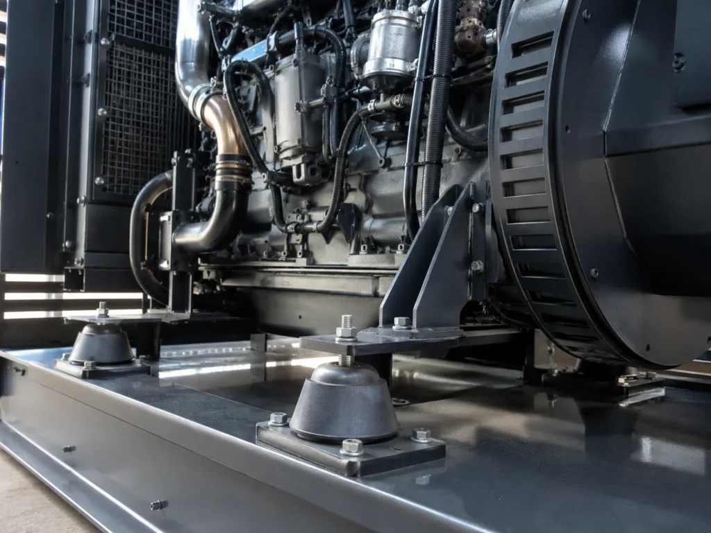
Why does mechanical vibration affect equipment performance?
Vibrations generated during mechanical operation typically originate from the following sources:
- Mass imbalance in rotating components
- Periodic excitation from motors, fans, or pumps
- Reciprocating motion of pistons, connecting rods, etc.
- Gear meshing
- Shaft misalignment
- Bearing clearance or wear
- Fluid pulsations
- Start-stop shocks
- Vibrations transmitted from the road surface or external structures
- Intermittent impact loads during the machining process
These vibrations do not necessarily cause immediate equipment failure, but they create continuously varying dynamic loads. Unlike static weight, dynamic loads constantly change in direction and amplitude, which can easily lead to loosening of fasteners, fatigue at connection points, increased stress in piping, and fluctuations in measurement signals.
Even low levels of unanticipated vibration can affect industrial process monitoring and precision measurements; higher levels of vibration can also cause structural damage, reduced product quality, discomfort to personnel, and airborne noise. When it is not possible to redesign equipment at the source, controlling the transmission path between the vibration source and the structure being protected is often an effective method of vibration control.
How Do Anti-Vibration Mounts Work?
You can think of a rubber vibration isolation mount system as a system composed of mass, a spring, and damping.
The equipment itself represents the mass, the rubber elastomer acts as the spring, and the energy dissipation within the rubber provides damping.
When the equipment vibrates, the rubber undergoes compression, shear, or combined deformation. Part of the mechanical energy is temporarily stored in the elastomer and subsequently released; another portion of the energy is converted into heat through the internal loss of the rubber material. Ultimately, the vibration energy transmitted to the frame, foundation, or vehicle body structure is reduced.
However, what truly determines the effectiveness of vibration isolation is not “whether the rubber can deform,” but rather whether the following parameters are properly matched:
- Equipment weight
- Actual load at each mounting point
- Excitation frequency
- Natural frequency of the vibration isolation system
- Dynamic stiffness of the rubber
- Damping level
- Mounting orientation
- Center of Gravity
- Allowable Displacement
Vista Motion’s technical specifications for rubber vibration isolation mounts also emphasize that the function of rubber mounts is to isolate the vibration source from the supporting structure and reduce the efficiency with which vibrations are transmitted from the equipment to the mounting surface, rather than simply raising the equipment off the ground.
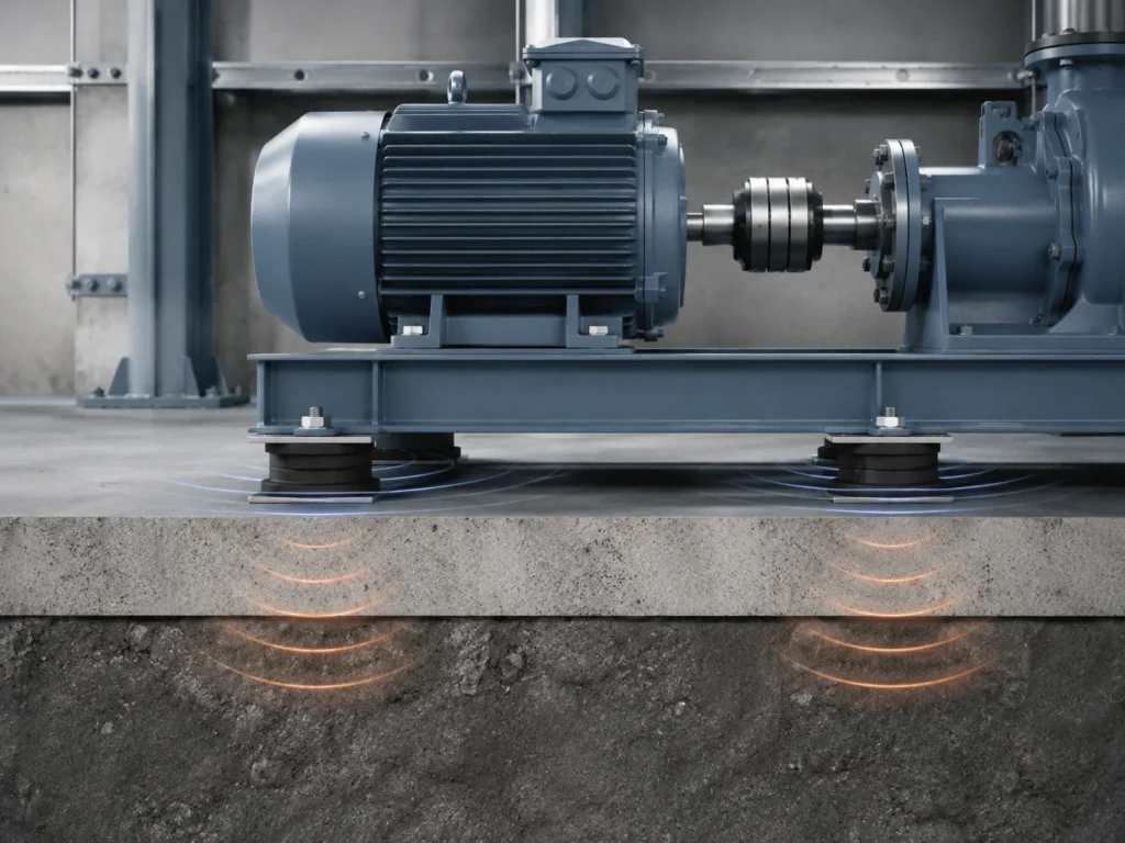
Natural Frequency, Excitation Frequency, and Frequency Ratio
One of the most important concepts in understanding anti-vibration mounts is the frequency ratio.
The frequency ratio can be expressed as: Frequency Ratio = Equipment Excitation Frequency ÷ Natural Frequency of the Vibration Isolation System
Equipment excitation frequencies typically result from motor rotational speed, engine operating frequency, gear meshing, or reciprocating motion. For rotating equipment, provides a preliminary conversion formula: Frequency (Hz) = Rotational Speed (RPM) ÷ 60
For example, when a piece of equipment operates at 1,800 RPM, its first-order rotational frequency is 30 Hz. However, actual equipment may also exhibit blade-passing frequencies, gear-meshing frequencies, and harmonic components, so it is not sufficient to consider only a single frequency.
When the excitation frequency approaches the natural frequency of the vibration isolation system, the system is prone to entering the resonance zone. In this case, installing vibration-damping mounts may cause the vibration to increase rather than decrease.
Only as the frequency ratio gradually increases will the system enter the vibration isolation zone. The goal of engineering design is typically not simply to select softer rubber, but to strike a balance between vibration isolation performance, equipment displacement, stability, and service life.
Vista Motion’s current selection guidelines recommend that engineers first confirm the actual load, minimum excitation frequency, and target vibration isolation performance, and then select the appropriate product based on load-displacement curves, dynamic stiffness data, and on-site verification.
How Do Anti-Vibration Mounts Improve the Performance of Mechanical Equipment?
Reducing the Transmission of Vibrations to Foundations and Frames
The most direct function of anti-vibration mounts is to reduce the efficiency with which dynamic forces generated by equipment are transmitted to the supporting structure.
When pumps, motors, or compressors are mounted directly on a rigid foundation, equipment vibrations are transmitted to:
- Steel structural frames
- Concrete foundations
- Piping systems
- Protective enclosures
- Equipment housing
- Adjacent production lines
- Building floors
These structures may further amplify vibrations at certain frequencies and generate audible structural noise.
When suitable machinery vibration isolators are installed between the equipment and its foundation, the vibration transmission path is isolated by the elastic elements. While the equipment itself may still vibrate to some extent, the vibrations transmitted to the foundation and surrounding structures are typically reduced.
This is particularly important for machinery installed on floor slabs, steel platforms, vehicle chassis, or integrated equipment frames.
Improving Equipment Operational Stability
Operational stability means not only that the equipment “does not appear to wobble,” but also that its posture, connections, and dynamic response are more controllable.
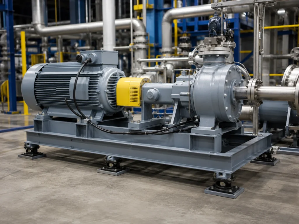
Take a pump set as an example: if the load is unevenly distributed across the four support points, one rubber anti-vibration mount may be subjected to excessive pressure, while another may experience almost no effective compression. The result could be:
- Equipment tilt
- Uneven stress on pipe connections
- Excessive sway during start-up and shutdown
- Premature failure of some mounts
- Actual vibration isolation performance falling short of design specifications
Properly designed anti-vibration mounts are matched to the equipment’s center of gravity and the loads at each support point, ensuring that each mounting point operates within a reasonable range of deflection.
For equipment with a high center of gravity, lateral forces, or mobile operating conditions, lateral stiffness, shear deformation, and anti-disengagement mechanisms must also be considered; it is not sufficient to calculate only the vertical weight.
Reduce the additional dynamic loads on components
Continuous vibration subjects mechanical joints to repeated, minute alternating loads. After prolonged operation, these loads may accelerate wear or fatigue in the following components:
- Bolts and fasteners
- Welded joints
- Bearing housings
- Pipe fittings
- Electrical connectors
- Sensor Mounts
- Metal Brackets
- Seals
- Thin-walled enclosures
Appropriate vibration damping mounts can reduce the level of vibration transmitted to these structures, thereby minimizing unnecessary dynamic stress.
However, this does not mean that installing vibration-damping mounts will automatically extend the service life of all components. Internal equipment failures, insufficient lubrication, material defects, and overloading can still cause damage. The value of vibration-damping mounts lies in reducing the additional loads caused by vibration transmission, not in eliminating all causes of failure.
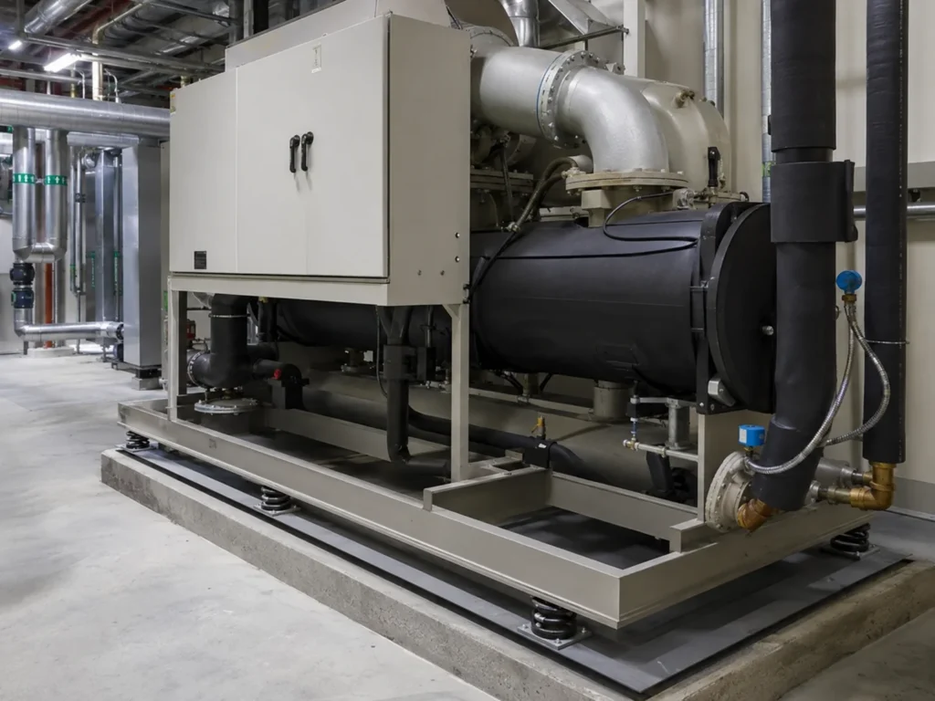
Improving Operating Conditions for Machine Tools and Precision Equipment
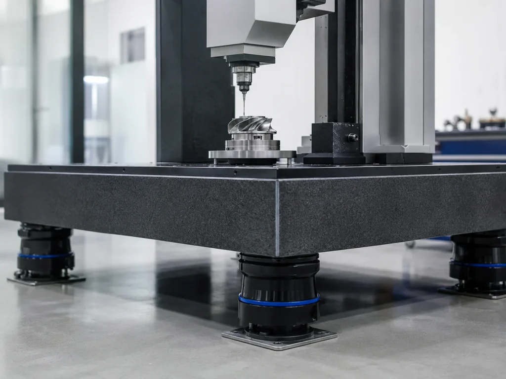
For ordinary fans, a small amount of vibration may manifest only as noise; however, for machine tools, testing equipment, or precision instruments, the same level of vibration can directly affect machining and measurement results.
External or internal vibrations may cause:
- Relative Displacement Between the Cutting Tool and the Workpiece
- Vibration marks appear on the machined surface
- Decreased repeatability
- Fluctuations in measurement signals
- Sensor noise
- Unstable imaging from optical equipment
- Decreased precision assembly consistency
Applications of this type require consideration of two aspects simultaneously: first, preventing the equipment’s own vibrations from being transmitted outward; and second, preventing vibrations from the floor, adjacent machinery, or building structures from being transmitted into the equipment.
Consequently, vibration isolation designs for precision equipment are typically more complex than those for ordinary industrial equipment. It is difficult to determine the actual effectiveness based solely on rubber hardness or product dimensions; it is also necessary to analyze the equipment’s natural frequencies, the mounting foundation, and the environmental vibration spectrum.
Reducing Structural Noise
Mechanical noise does not originate entirely from the air.
When equipment vibrations are transmitted to steel frames, floors, walls, or enclosures, these structures can radiate sound into the surrounding environment much like a speaker diaphragm. This type of noise is commonly referred to as structure-borne noise.
Anti-vibration rubber mounts can reduce noise generated by structural radiation by minimizing the vibrations transmitted to the structure.
However, it is important to distinguish between two scenarios:
- If the noise is primarily caused by structural vibration, anti-vibration mounts are generally effective;
- if the noise stems from high-speed airflow, exhaust, gear meshing, or fan blades, silencers, sound enclosures, or other acoustic measures are still required.
Therefore, one cannot simply conclude that softer vibration-isolation mounts are needed just because “the equipment is noisy.” The correct approach is to first identify the noise source and the primary transmission path.
Reducing Vibration Interference with Surrounding Equipment
In a factory setting, vibrations generated by one piece of equipment may be transmitted to another via a shared foundation or steel platform.
For example:
- Stamping equipment interfering with nearby measuring instruments
- Compressor vibrations transmitted to the control cabinet
- Vibrations from a generator set are transmitted into the building floor
- Vibrations from a pump set travel along the piping
- Fan vibrations transmitted to the ventilation system housing
- Machining equipment affecting adjacent precision workstations
Industrial anti-vibration mounts can create an isolation layer near the vibration source to reduce the transmission of vibrations into the building structure.
However, vibration isolation mounts are only one component of the system. Piping, cables, exhaust pipes, rigid stops, and safety tie rods can all create new vibration transmission paths. Even if the mounts are correctly selected, the overall effectiveness will still be significantly reduced if bypass connections are too rigid.
Improving Equipment Start-up, Shutdown, and Impact Conditions
Some equipment is subject not only to continuous, cyclic vibrations but also to transient impacts, such as:
- Engine start-up and shutdown
- Compressor loading and unloading
- Road impacts on construction machinery
- Machine tool tool engagement
- Emergency stops of equipment
- Vibration During Transportation of Mobile Equipment
- Changes in Ship or Vehicle Attitude
For these operating conditions, vibration-damping mounts must account not only for steady-state frequencies but also for instantaneous displacement, peak loads, and anti-disengagement requirements.
Standard cylindrical rubber mounts may be suitable for steady-state compressive loads, but they are not necessarily suitable for significant lateral impacts. For equipment subject to significant impacts or changes in installation orientation, the following may be required:
- Conical vibration-damping mounts
- Center-bonded mounts
- Vibration isolators with stop mechanisms
- Multi-directional load-bearing structures
- Failure-safe design
- Pre-stressed or Bidirectionally Constrained Structures
Improving the Predictability of Maintenance Outcomes
Vibration increases the randomness of changes in equipment condition. Fasteners, brackets, or cables of the same model may exhibit significantly different service lives under different vibration conditions.
When anti-vibration mounts are properly applied, the dynamic loads transmitted from the equipment to the surrounding structure are easier to control, making it simpler for maintenance teams to establish consistent inspection schedules.
Key monitoring points:
- Compression of mounts
- Rubber cracking
- Delamination between metal and rubber
- Loose fasteners
- Permanent deformation of bearings
- Changes in equipment orientation
- Induced stresses in piping
- Corrosion at Installation Points
Anti-vibration mounts themselves are components susceptible to environmental factors and fatigue; they must be included in preventive maintenance programs and should not be left uninspected for extended periods after installation.
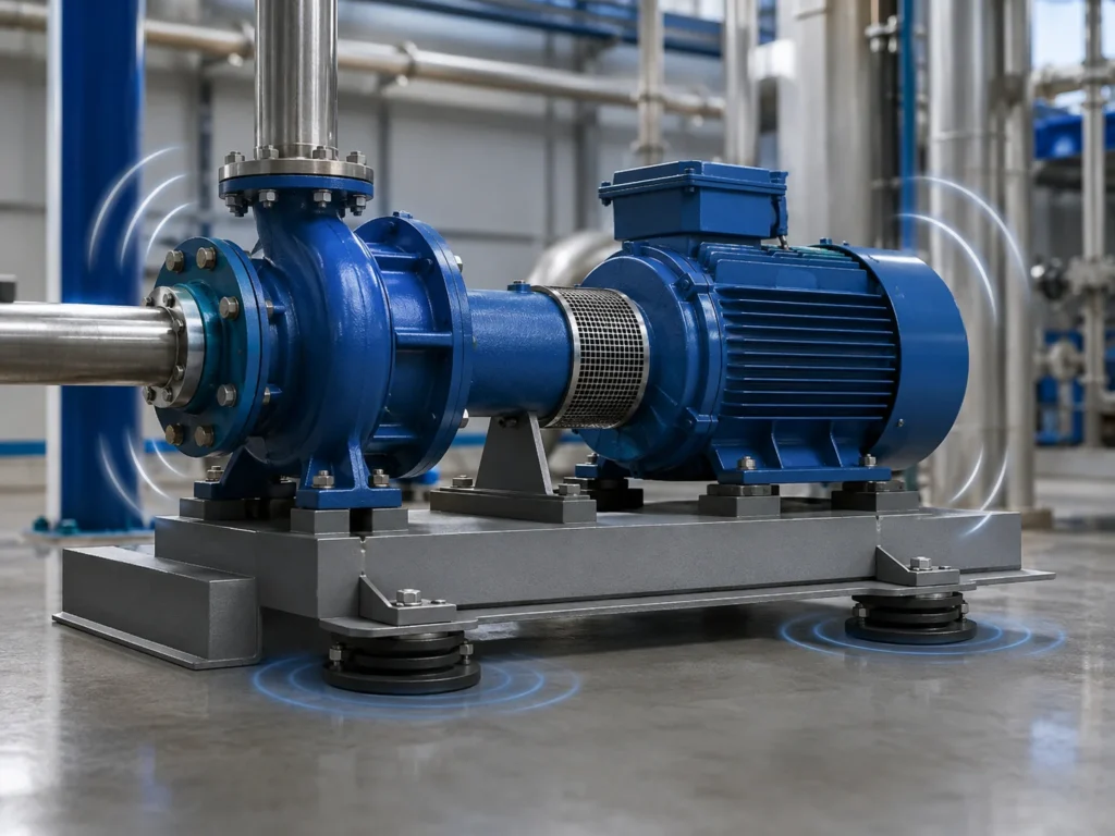
What are the differences between various types of anti-vibration mounts?
| Type | Key Features | Common Applications | Points to Note |
| Compression-Type Rubber Mounts | Good vertical load-bearing capacity; simple structure | Motors, pumps, and small machinery | Lateral flexibility is typically limited |
| Shear-Type Rubber Bearings | Easily achieves large deflections and low stiffness | Fans, equipment platforms, side-mounted equipment | Requires control of lateral displacement |
| Cylindrical/Bobbin Mounts | Easy to install, with a wide range of models available | Motors, instruments, control cabinets | Not suitable for all multi-axis shock conditions |
| Conical Mounts | Provide both vertical support and lateral cushioning | Engines, vehicles, construction machinery | Installation orientation and preload must be verified |
| Sandwich Mounts | Alternating layers of rubber and metal plates | Heavy-duty equipment, shear conditions | Edge stress and bond quality are critical |
| Center-Bonded Mounts | Strong multidirectional vibration isolation and shock control capabilities | Engines, compressors, mobile equipment | Selection must consider both center of gravity and dynamic loads |
| With stop brackets | Limits excessive displacement and provides anti-disengagement protection | Vehicles, ships, and impact-prone equipment | Excessively small limit clearance may cause a rigid short circuit |
No single design is suitable for all machinery.
When selecting a product, first confirm the load direction and vibration characteristics, then determine the product structure. Simply searching for replacement parts based on external dimensions usually only ensures a “proper fit” but does not guarantee consistent vibration isolation performance.
How do rubber materials affect vibration damping performance?
Different rubber materials vary in their oil resistance, weather resistance, temperature range, dynamic performance, and aging characteristics.
| Rubber Materials | Typical Advantages | Common Operating Environments |
| NR (Natural Rubber) | Good elasticity and dynamic fatigue resistance | General industrial vibration isolation |
| NBR Nitrile Rubber | Good oil resistance | Equipment that comes into contact with fuel, lubricating oil, or hydraulic fluid |
| CR (Chloroprene Rubber) | Combined resistance to weathering, ozone, and certain oils | General outdoor and industrial environments |
| EPDM (Ethylene Propylene Diene Monomer) rubber | Good resistance to ozone, weathering, and water | Outdoor, humid, and environmentally exposed equipment |
| Silicone rubber | Suitable for a wide temperature range | High and low temperatures or special environments |
The material name alone does not determine the final performance. For the same type of rubber, dynamic stiffness and fatigue life may vary significantly depending on differences in formulation, hardness, fillers, vulcanization state, and structural shape.
Therefore, when purchasing custom anti-vibration mounts, specifications should not be limited to “material: NBR” or “hardness: 60 Shore A.” More comprehensive technical requirements should also include:
- Operating temperature
- Contact medium
- Static Load
- Dynamic load
- Excitation frequency
- Allowable Displacement
- Target Service Life
- Environmental Aging Requirements
- Metal Corrosion Protection Requirements
- Bond Strength or Failure Mode Requirements
How to Select the Right Anti-Vibration Mounts?
Step 1: Determine the Vibration Isolation Objective
First, identify the problem you actually need to solve:
- Reduce foundation vibration
- Reduce structural noise
- Protecting precision equipment
- Absorbing impacts
- Limiting equipment displacement
- Improve operational comfort
- Reduce fatigue in piping or supports
Different objectives may require different stiffness and damping designs.
For example, to reduce structural noise, it is generally desirable to minimize vibration transmission; however, for mobile machinery, mounts must also limit excessive displacement of the engine or equipment.
Step 2: Calculate the actual load at each support point
Do not use the following formula directly: Total equipment weight ÷ Number of supports
If the equipment’s center of gravity is not at the geometric center of the mounting plane, the load borne by each support may vary. The arrangement of the motor, gearbox, pump housing, and accessories can all alter the center of gravity.
The correct approach is to calculate the actual load on each support point based on the location of the center of gravity, the coordinates of the support points, and the installation orientation.
Uneven loading may result in:
- Excessive compression at a particular support
- Some supports failing to reach their design deflection
- Equipment tilt
- Changes in the vibration isolation frequency
- Premature fatigue of local supports
Step 3: Determine the minimum operating frequency
Many selection errors occur because only normal high-speed operation of the equipment is considered, while startup, low-speed, or variable-frequency operating conditions are overlooked.
For variable-frequency motors, engines, or compressors, the following should be verified:
- Minimum continuous operating speed
- Frequency range during start-stop cycles
- Idle speed
- Output speed after gear reduction
- Operating frequency of reciprocating mechanisms
- Major overtones and harmonics
Low-frequency vibrations are generally more difficult to isolate than high-frequency vibrations. A mount that performs well at rated speed may enter the resonance range during startup or at low speeds.
Step 4: Determine the Mounting Orientation
Rubber exhibits different stiffness in the compression and shear directions.
For the same rubber-to-metal mount:
- When installed vertically, it may primarily experience compression;
- When installed laterally, it may primarily experience shear;
- When installed at an angle, it may be subjected to a combination of loads;
- In automotive applications, it may also be subjected to tensile, torsional, and impact loads.
Therefore, suppliers need to know the product’s actual installation orientation, not just a single part drawing.
Step 5: Select the Appropriate Static Deformation
Static deformation refers to the compression or shear displacement of the bearing when it supports the weight of the equipment.
Generally, all other conditions being equal, a larger static deflection helps reduce the system’s natural frequency. However, excessive static deflection can also result in:
- Equipment sway
- Reduced installation stability
- Increased displacement at pipe joints
- Excessive rubber strain
- Long-term creep
- Collision with limit stops
- Reduced bearing service life
Therefore, one cannot simply assume that “softer is better” or “the more compression, the better.”
Step 6: Confirm Environmental Conditions
The following environmental factors directly affect rubber materials and metal structures:
- Lubricating oil
- Hydraulic fluid
- Fuel
- Coolant
- Ozone
- Ultraviolet
- Salt spray
- High humidity
- High or low temperatures
- Acidic or alkaline environments
- Outdoor exposure
Using the wrong materials may result in swelling, hardening, cracking, or delamination after a period of operation, even if the initial vibration isolation performance meets requirements.
Step 7: Check the Installation Space and Safety Requirements
The following must be confirmed:
- Support height
- Thread specifications
- Mounting hole locations
- Allowable Compression
- Lateral Clearance
- Maintenance Space
- Fail-safe Protection Required
- Is an anti-disengagement mechanism required?
- Is height adjustment required?
- Is there a risk of overturning?
For equipment with a high center of gravity, supports that are too soft may reduce lateral stability. In such cases, one should not merely pursue a lower natural frequency; it is also necessary to analyze the risk of equipment swaying and overturning.
Step 8: Verification Using Dynamic Data
The dynamic stiffness of rubber typically differs from its static stiffness and is influenced by the following factors:
- Frequency
- Temperature
- Amplitude
- Preload
- Rubber Formulation
- Service Life
- Environmental Aging
Therefore, calculating vibration isolation performance based solely on hardness and static compression may result in inaccuracies.
For critical equipment, it is recommended to consider both:
- Load–displacement curves
- Dynamic stiffness
- Transmission ratio
- Natural frequency
- Fatigue testing
- Temperature Aging Test
- Rubber-to-Metal Bonding Validation
- Vibration Measurements Before and After On-Site Installation
The ISO 10846 series of standards covers laboratory measurements of the vibration and acoustic transmission characteristics and dynamic stiffness of elastic elements; the ISO 20816 series provides a general framework for the measurement and evaluation of mechanical vibrations. Specific standards should be selected based on the equipment type and customer requirements.
How to Determine if Anti-Vibration Mounts Are Effective?
Do not rely solely on touching the equipment with your hands or on auditory judgment.
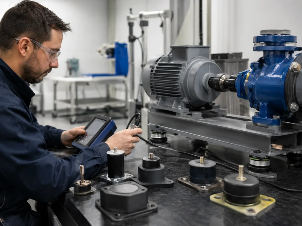
A more reliable method is to compare data collected before and after installation under identical operating conditions.
Ensure Consistent Test Conditions
When comparing pre- and post-installation data, the following conditions should be maintained:
- The same equipment speed
- The same load
- Same measurement points
- The same measurement direction
- The same sensor mounting method
- Same sampling settings
- Same pipeline and fitting conditions
Otherwise, the data may not be comparable.
Measure both the vibration source and the receiving end simultaneously
The following can be measured separately:
- Equipment housing
- Above the support
- Below the mount
- Foundation or frame
- Connecting piping
- Adjacent equipment mounting points
This allows you to determine whether the vibration is reduced at the source or isolated along the transmission path.
Record data during multiple operating phases
The following should be covered:
- Start-up
- Low speed
- Normal operation
- Full load
- Unloading
- Shutdown
Some bearings perform well at rated speed but exhibit noticeable vibration when starting up and passing through the resonance frequency.
Check the static compression
After installation, check whether the actual deflection of each bearing is close to the design value.
If a bearing shows almost no compression, this may indicate uneven load distribution; if the deflection is excessive, it may indicate overloading, selection of a bearing that is too soft, or an error in the calculation of the center of gravity.
Check for Rigidity Short-Circuits
Common causes of vibration short-circuiting include:
- Excessively rigid connecting piping
- Taut cables
- Rigid exhaust pipe connections
- Direct contact with limit switches
- Safety tie rods with no clearance
- Mounting bolts locked in place Elastic structure
- Guard in contact with the foundation
Mechanical connections with high rigidity may bypass the anti-vibration mounts, reducing the actual performance of the entire vibration isolation system.
Common Selection and Installation Errors
Focusing solely on load capacity
Rated load capacity is important, but load-bearing capacity does not equate to vibration isolation effectiveness.
Selecting mounts with excessively high stiffness may easily support the weight but result in virtually no effective deformation, making the entire installation nearly equivalent to a rigid connection.
Assuming that Harder Rubber Is More Durable
Higher rubber hardness typically indicates greater load-bearing capacity, but it may also increase vibration transmission.
Hardness should be determined based on the load, structure, materials, and target dynamic performance, rather than used solely as a criterion for assessing quality.
The belief that softer rubber provides better vibration isolation
A bearing that is too soft may cause excessive equipment displacement, unstable orientation, piping tension, and excessive rubber strain.
Low stiffness must be considered in conjunction with safety clearances, limit stops, and center-of-gravity stability.
Ignoring the minimum rotational speed
Selecting a model based solely on the rated speed may cause the equipment to enter the resonance range during low-speed operation or startup.
Using the Same Stiffness at All Support Points
When the equipment’s center of gravity is significantly offset, different support points may require different load-bearing specifications.
Directly Replacing with Products of the Same Dimensions
Two anti-vibration mounts with identical external dimensions may have completely different rubber formulations, hardness, dynamic stiffness, and bonding structures.
Ignoring the quality of the rubber-to-metal bond
Rubber-to-metal mounts operate under repeated shearing, compression, and temperature fluctuations. If the metal surface treatment, adhesive system, or vulcanization process is inconsistent, edge cracking or delamination at the interface is likely to occur.
Failure to verify performance after installation
Without measurement and inspection, it is impossible to confirm whether the actual vibration isolation performance meets the target specifications.
Which Mechanical Equipment Is Suitable for Anti-Vibration Mounts?
Anti-vibration mounts are widely used in:
- Pumps and pump sets: To reduce the transmission of vibrations generated by motors, impellers, and fluid pulsations to the base and piping.
- Air compressors: To control vibrations caused by rotation, reciprocating motion, and load switching, while reducing dynamic loads on the frame and piping.
- Generator sets: To isolate vibrations caused by engine combustion excitation, rotational imbalance, and start-stop impacts, and to control the transmission of vibrations to the chassis or building structure.
- Motors and fans: To reduce structural noise caused by rotational imbalance, blade-passing frequencies, and housing vibrations.
- Industrial Engines: Engine mounts must simultaneously support weight, control torque reaction forces, reduce vibration, and limit powertrain displacement.
- Machine Tools: Used to isolate external ground vibrations or reduce the transmission of the equipment’s own vibrations to surrounding precision workstations.
- HVAC Equipment: Fans, chillers, air conditioning units, and cooling equipment can use vibration-isolating mounts to reduce floor vibrations and structural noise.
- Construction Machinery and Mobile Equipment: These must withstand multidirectional vibrations, impacts, tilting, and harsh environments, so they typically require custom anti-vibration mounts with stop or anti-disengagement mechanisms.
- Control Cabinets and Electronic Equipment: Used to protect internal electronic components, wiring, and sensors from continuous vibration or transportation shocks.
When Are Custom Anti-Vibration Mounts Needed?
Standard products are suitable for applications with clearly defined operating conditions, stable loads, and standard installation spaces.
Consider a custom solution in the following situations:
- Installation dimensions do not match those of standard products
- The equipment’s center of gravity is significantly offset
- Simultaneous exposure to compressive, shear, and tensile loads
- Significant start-stop impacts are present
- Protection against disengagement or failure is required
- Special operating temperatures
- Exposure to hydraulic fluid, salt spray, or chemical media
- Has specific requirements for dynamic stiffness
- Target requirements for natural frequency or transmission ratio
- Requires matching metal brackets or connectors
- Requires integrated vulcanization of rubber and metal
- Requires batch consistency and traceability
- Standard mounts cannot simultaneously meet vibration isolation and stability requirements
Customization is not merely a matter of changing dimensions. The development of true custom anti-vibration mounts typically involves:
- Operating condition and load analysis;
- Selection of rubber materials and hardness;
- Metal structure design;
- Optimization of stress concentrations and deformation paths;
- Mold and vulcanization process design;
- Control of rubber-to-metal bonding;
- Prototype Production;
- Dynamic and durability validation;
- Consistency control in mass production.
What information should be prepared before requesting a quote from a supplier?
To obtain more accurate product recommendations, we recommend providing the following information:
- Total weight of the equipment
- Center of gravity location
- Number and coordinates of support points
- Actual load at each mounting point
- Minimum and maximum operating speeds
- Principal excitation frequency
- Mounting orientation
- Vibration direction
- Maximum impact load
- Permissible Equipment Displacement
- Operating Temperature
- Contact Medium
- Mounting Dimensions
- Threads and Hole Locations
- Operating Environment
- Target Vibration Isolation Performance
- Expected Service Life
- Annual Demand
- Drawings or Existing Samples
The more complete the information provided, the easier it will be for suppliers to determine whether to use standard machine mounts or develop custom rubber-metal vibration damping components.
Summary
Anti-vibration mounts improve the performance of mechanical equipment primarily by controlling vibration transmission paths.
When load, frequency, natural frequency, dynamic stiffness, mounting orientation, and environmental conditions are properly matched, anti-vibration mounts can help:
- Reduce the transmission of vibration to the foundation and frame
- Reduce structure-borne noise
- Improve equipment operational stability
- Protect fasteners, piping, and peripheral components
- Create more stable conditions for precision machining and measurement
- Reduce vibration interference between adjacent equipment
- Make maintenance and operational status easier to predict
Vista Motion can assist in evaluating rubber materials, hardness, metal structures, installation methods, and validation requirements based on customer drawings, samples, and actual operating conditions.According to information published on Vista Motion’s official website, its service scope includes rubber-to-metal bonding, compression or injection molding, metal part manufacturing, surface treatment, prototype development, and related strength and durability validation. The company emphasizes process traceability and quality control under the IATF 16949 and ISO 9001 systems.
If your project involves pumps, compressors, generators, industrial engines, machine tools, vehicle equipment, or other industrial machinery, you can provide details such as equipment weight, rotational speed, center of gravity, mounting orientation, environmental conditions, and target vibration isolation requirements. Based on this information, Vista Motion will determine whether standard anti-vibration mounts are suitable or if custom rubber-to-metal vibration mounts need to be developed, thereby reducing the risk of selection errors and subsequent modifications starting from the prototype validation stage.
How do anti-vibration mounts work?
Anti-vibration mounts reduce the transmission of equipment vibrations to the frame, foundation, and surrounding structures through the deformation and damping effects of rubber or other elastic materials. When subjected to force, the rubber stores and releases some of the energy while dissipating part of the mechanical energy through internal losses.
They primarily control vibration transmission paths and do not automatically correct faults such as equipment imbalance, bearing damage, or misalignment.
Can anti-vibration mounts really improve the performance of mechanical equipment?
Yes, provided they are properly selected and installed.
Appropriate anti-vibration mounts can reduce structural vibration, lower noise, improve equipment alignment, and reduce the additional dynamic loads on piping, fasteners, and peripheral structures. For machine tools and measuring equipment, they can also help create a more stable working environment.
If the stiffness, load, or natural frequency of the mounts are mismatched, equipment vibrations may actually be amplified.
How do you select anti-vibration mounts for mechanical equipment?
At a minimum, the following must be confirmed:
- The actual load at each support point
- The lowest operating frequency
- Installation orientation
- Center of gravity
- Target vibration isolation performance
- Allowable displacement
- Operating Temperature
- Contact Medium
- Are there impact loads?
- Is an anti-disengagement or limit stop mechanism required?
Selection should not be based solely on dimensions, rubber hardness, or rated load.
Do softer rubber vibration-isolation bearings provide better vibration isolation?
Not necessarily.
Softer rubber typically deforms more easily, which helps lower the natural frequency, but it may also cause equipment sway, excessive compression of the bearing, and reduced lateral stability.
A balance should be struck between vibration isolation performance, load-bearing capacity, equipment displacement, and service life.
Do harder rubber vibration-isolation bearings have a longer service life?
This is not necessarily the case.
Harder rubber generally has higher stiffness and load-bearing capacity, but may transmit more vibration. Actual service life also depends on the rubber compound, dynamic strain, temperature, fluids, ozone, structural design, bond quality, and vulcanization process.
What is the difference between rubber mounts and vibration isolators?
These two terms are often used interchangeably.
“Rubber mounts” emphasize the material and mounting structure, while “vibration isolators” emphasize the vibration isolation function. Not all rubber mounting components have the same vibration isolation performance, nor do all vibration isolators use rubber; springs, steel cables, and air springs can also be used for vibration isolation.
Why does equipment vibration actually increase after installing vibration-damping mounts?
Common causes include:
- The excitation frequency is close to the system’s natural frequency
- The stiffness of the mounts is too high or too low
- Uneven load distribution on the mounts
- Failure to account for the minimum operating speed
- Equipment center of gravity is too high
- Pipes or cables forming a rigid short circuit
- Limit switches in direct contact with the structure
- Installation bolts incorrectly locking the elastic components
This needs to be reevaluated in light of the operating frequency, actual compression ratio, and installation configuration.
Can anti-vibration mounts reduce mechanical noise?
They can reduce noise caused by structural vibrations.
If equipment noise is primarily radiated through the foundation, housing, or steel frame, anti-vibration mounts are typically effective. However, for airflow noise, exhaust noise, gear meshing noise, or fan aerodynamic noise, additional acoustic control measures are required.
What rubber materials are typically used in anti-vibration mounts?
Common materials include NR (natural rubber), NBR (nitrile rubber), CR (chloroprene rubber), EPDM (ethylene propylene diene monomer rubber), and silicone rubber.
Material selection should be based on a comprehensive evaluation of dynamic performance, temperature, oils, ozone, UV exposure, humidity, and chemical exposure; it should not be based solely on the material name.
When should custom anti-vibration mounts be selected?
Customization should be considered when standard products cannot meet requirements for installation dimensions, dynamic stiffness, multidirectional loads, impact protection, environmental resistance, anti-detachment structures, or batch consistency.
Custom development should include material selection, structural design, rubber-to-metal bonding, prototype manufacturing, dynamic testing, and durability validation—rather than simply modifying the external dimensions.
